
Recent Posts
Mastering Bushing Tolerance of Fit: The Definitive Guide to Precision Engineering
Introduction: Why Tolerance of Fit Determines Success or Failure
Ever installed a bushing that felt right at first, only to have it seize up after an hour of operation? Or watched a seemingly perfect fit spin loose in its housing, chewing up expensive machinery? If you have, you already know the culprit wasn’t luck—it was tolerance.
Here’s the thing about bushings: they live at the intersection of motion and support. Get the fit wrong by a few microns, and you’re looking at overheating, vibration, premature wear, or catastrophic failure. Get it right, and your equipment runs smoothly for years with minimal maintenance.
This guide walks through everything you need to know about bushing tolerance of fit—from basic concepts to practical selection criteria. And when you’re ready for components that hold tolerance under real-world conditions, MYWAY’s precision engineering delivers exactly what your drawings specify.
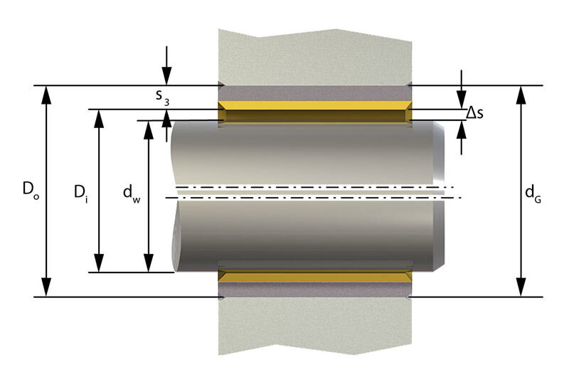
Table of Contents
1. Understanding Bushing Tolerance Fundamentals
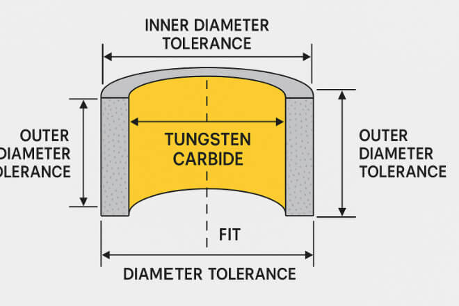
What Is Tolerance of Fit?
Tolerance refers to the permissible variation in a component’s dimensions. Fit describes how two mating parts—like a bushing and its housing, or a shaft and a bushing—interact with each other. Together, tolerance of fit determines whether assembly is possible and whether the assembly functions as intended.
For bushings specifically, we’re dealing with three critical interfaces:
Bushing outer diameter to housing bore (static connection)
Bushing inner diameter to shaft (dynamic interface)
Bushing length to housing width (axial positioning)
Each interface requires different considerations. The housing fit needs to prevent rotation and fretting. The shaft fit needs to allow controlled movement while maintaining a lubricant film. Both depend on properly specified tolerances.
Why Standardization Matters
Engineers don’t reinvent the wheel with every design. International standards provide common language and predictable outcomes:
ISO 286 defines the global system for limits and fits
ANSI B4.1 covers inch-based fits primarily used in North America
DIN ISO 286 adapts the ISO system for German applications
JIS B 0401 serves Japanese manufacturing
These standards ensure that when you specify H7 on a drawing, machine shops in Shanghai, Detroit, or Stuttgart all understand exactly what you mean.
Tolerance Zones Explained
Every dimension exists within a range. The tolerance zone represents that range—the space between upper and lower deviation limits. When a shaft and hole share the same basic size, how these zones overlap determines the resulting fit.
Think of it this way: if the shaft’s tolerance zone sits completely below the hole’s zone, you get guaranteed clearance. If it sits completely above, you get guaranteed interference. Overlap? That’s transition fit territory.
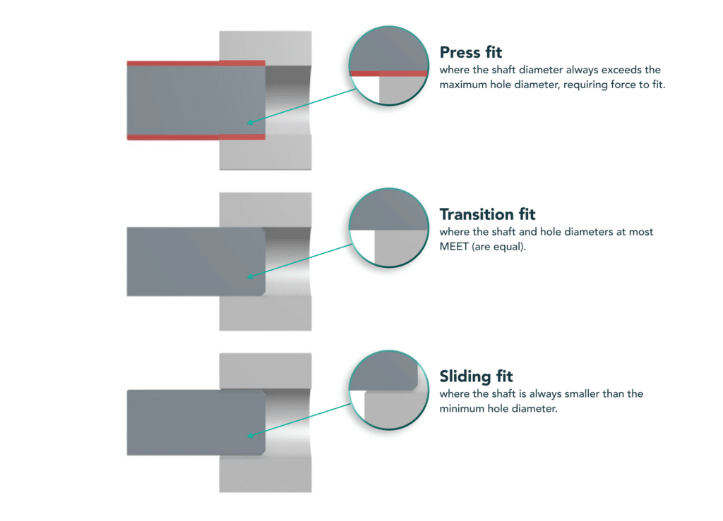
2. The Three Types of Fits: Clearance, Interference, and Transition
Clearance Fit: When Parts Need to Move
A clearance fit guarantees space between components. Even at maximum material conditions (largest shaft, smallest hole), some gap remains.
Characteristics of clearance fits:
Measurable clearance under all conditions
Low friction operation
Tool-free or light press assembly
Designed for relative motion
When to choose clearance fits:
Rotating shafts inside bushings
Linear sliding applications
Oscillating movements
Any application requiring lubrication film formation
Common designations: H7/g6 (precision running), H7/f7 (free running), H9/d9 (loose running)
For shaft-to-bushing interfaces in plain bearings, clearance fits are typically the right choice. A shaft tolerance of g6 or f7 paired with an H7 housing after installation provides predictable operating clearance.
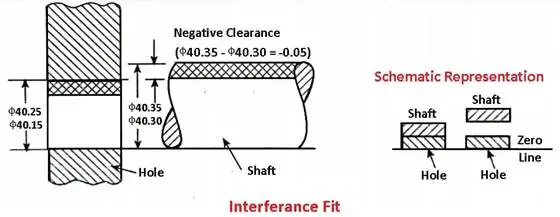
Interference Fit: When Parts Must Become One
An interference fit creates overlap—the shaft (or bushing OD) is intentionally larger than the hole it goes into. Assembly requires force, temperature differentials, or both.
Characteristics of interference fits:
Guaranteed interference under all conditions
High holding strength without additional fasteners
No relative motion between components
Requires pressing, heating, or cooling for assembly
Difficult or destructive disassembly
When to choose interference fits:
Pressing bushings into housings
Permanent anchoring applications
High-load structural joints
Torque-transmitting connections
Common designations: H7/p6 (light press), H7/s6 (heavy press), H7/u6 (severe press)
For bushing outer diameters, interference fits prevent “bushing spin”—that destructive condition where the bushing rotates in its housing, generating heat and wearing away both components. Most manufacturers recommend H7 housing tolerance with p6 or r6 bushing OD tolerance.
Transition Fit: The Best of Both Worlds
Transition fits occupy the middle ground. Depending on actual manufactured dimensions, the assembly might result in slight clearance or slight interference.
Characteristics of transition fits:
Can be either clearance or interference
Provides accurate centering
Allows controlled assembly force
Easier to disassemble than full interference
Requires tighter process control
When to choose transition fits:
Precision locating applications
Components needing frequent service access
Situations where centering matters more than holding force
Alignment-critical assemblies
Common designations: H7/k6 (locational transition), H7/js6 (close transition)
Quick Reference: Fit Types Comparison
| Feature | Clearance Fit | Interference Fit | Transition Fit |
|---|---|---|---|
| Result | Always gap | Always overlap | Could be either |
| Zone Position | Shaft fully below hole | Shaft fully above hole | Zones overlap |
| Assembly | Hand assembly | Force or temperature | Light force |
| Motion | Allowed | Prevented | Minimal |
| Typical Use | Rotating shafts | Housing mounting | Precise alignment |
| ISO Examples | H7/g6, H7/f7 | H7/p6, H7/s6 | H7/k6, H7/js6 |
3. The Hole Basis System: Industry Standard for Bushing Design
Why H7 Dominates Bushing Specifications
If you’ve spent any time with bushing drawings, you’ve noticed H7 everywhere. There’s a practical reason for this.
The hole basis system fixes the hole tolerance (usually with lower deviation of zero) and varies the shaft tolerance to achieve different fits. For bushings, the “hole” in question is the housing bore.
This system dominates because:
Holes are harder to modify than shafts
Standard tooling (reamers, boring bars) establishes fixed hole sizes
Shafts can easily be ground to different tolerances
Inspection is simpler with fixed hole gauges
The H7 Advantage: An H7 housing bore provides a consistent reference point. The bushing, when pressed in, will conform to this bore. After installation, the bushing’s inner diameter settles into a predictable range based on the interference amount and wall thickness.
Shaft Basis: When the Shaft Comes First
Sometimes the shaft is fixed—maybe it’s a existing component, a standard size, or part of a purchased assembly. In these cases, engineers use the shaft basis system, fixing the shaft tolerance and varying the hole.
Shaft basis fits use h as the reference (upper deviation zero). While less common for new designs, understanding both systems prevents confusion when reading legacy drawings or working with replacement parts.
4. Practical Bushing Tolerance Applications
Housing Fit: Securing the Bushing
The bushing-to-housing interface must prevent two failure modes: spinning and migration. Spinning happens when the bushing rotates in its housing, generating friction at the OD and usually wearing away the housing material. Migration refers to axial movement—the bushing gradually working its way out of position.
Recommended housing fits:
For most applications, engineers specify:
Housing bore: H7 tolerance
Bushing OD: p6, r6, or s6 depending on wall thickness and housing material
The interference typically ranges from 0.01 mm to 0.05 mm for smaller diameters, scaling with size. Steel and cast iron housings can accept standard interference. Light alloy housings may need additional interference due to different thermal expansion rates.
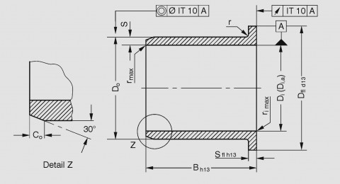
Special consideration for wrapped bushings: Unlike solid bushings, wrapped designs aren’t perfectly cylindrical in their free state. They only become round when pressed into the housing. This means you can’t accurately measure a wrapped bushing’s OD before installation—it will conform to the housing when the split closes.
Shaft Fit: Managing the Running Clearance
The shaft-to-bushing interface determines operating behavior. Too tight, and you risk seizure when temperatures rise. Too loose, and you lose precision and invite vibration.
Recommended shaft fits:
For general rotating applications:
Shaft tolerance: f7 or g6 (clearance fit with H7 bore after installation)
For higher precision: h6 (minimal clearance, requires excellent alignment)
For dirty environments: e7 or e8 (extra clearance for contamination)
The actual running clearance depends on:
Bearing material and its thermal expansion
Operating temperature range
Lubrication method and viscosity
Shaft hardness and surface finish
Load conditions
After pressing an H7/p6 bushing into an H7 housing, the inner diameter typically settles into an H8 or H9 range—slightly larger and with more variation than the original ID. This is normal and must be accounted for in shaft selection.
Length and Positioning
Bushing width tolerances affect assembly stack-up and end play. Most manufacturers hold width to ±0.25 mm or ±0.5 mm for standard products.
For flanged bushings, flange thickness and diameter have their own tolerances. The flange provides axial location, so these dimensions matter for positioning precision.
5. Material Considerations in Tolerance Selection
Metal Bushings: Predictable but Not Simple
Metallic bushings—bronze, brass, steel—behave predictably under load and temperature. Their thermal expansion coefficients are well-understood, and they don’t absorb moisture or swell over time.
Key metal bushing materials:
Tin Bronze (CuSn10): Excellent corrosion resistance, good for marine environments
Aluminum Bronze (CuAl10Fe5Ni5): High strength, corrosion resistant, good for high loads
Lead Bronze (CuPb10Sn10): Superior anti-friction properties, ideal for high temperatures
High-Strength Brass (CuZn25Al5): Excellent mechanical strength for impact loads
Each material responds differently to interference. Harder materials transfer more press force to the housing; softer materials deform more, potentially closing the ID more during installation.
Plastic Bushings: Accounting for Environment
Polymer bushings introduce additional variables. They absorb moisture, expand with temperature more than metals, and may creep under sustained load.
For plastic bearings:
Housing bore still H7 (or sometimes H8 for larger sizes)
Shaft tolerance typically h9 or h11 (more clearance than metal applications)
Press-fit oversize can reach 2% of inner diameter
Moisture absorption requires larger clearances for materials like nylon
The inner diameter of a plastic bushing only reaches its final size after press-fit into the housing. This “setting” process must be accounted for in tolerance calculations.
Self-Lubricating Bushings: The MYWAY Advantage
Self-lubricating bushings combine metal strength with built-in lubrication. MYWAY’s solid lubricating bushings embed graphite or molybdenum disulfide in precisely designed cavities within a bronze matrix.
During operation, frictional heat transfers these solid lubricants onto the contact surface, maintaining a low friction coefficient without external oil or grease. This technology eliminates maintenance while maintaining predictable running clearances.
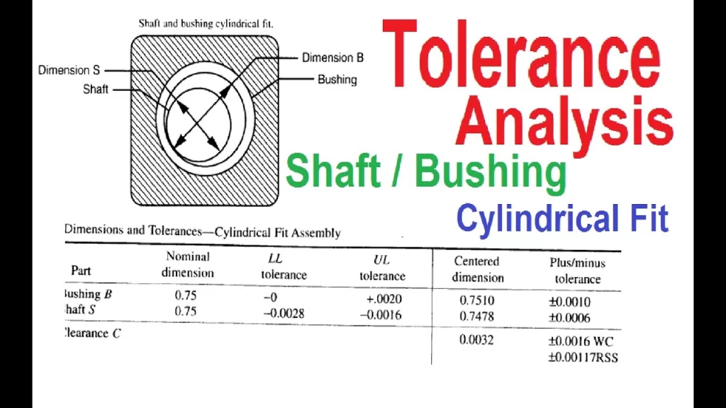
Temperature effects: At increased operating temperatures, bearing clearance reduces—about 0.0016 mm per 20°C for some materials. MYWAY’s thermal expansion coefficient of 16.5×10⁻⁶/K ensures predictable behavior across temperature ranges.
6. Installation Effects on Final Tolerances
What Happens During Press-Fit
Here’s where theory meets reality. Pressing a bushing into an undersized housing doesn’t just hold it in place—it actually changes the bushing’s dimensions.
During installation:
The outer diameter compresses radially
This compression transfers to the inner diameter
The ID becomes smaller than its free-state dimension
The amount of reduction depends on wall thickness and interference
A bushing with 0.03 mm interference might see its ID reduce by 0.015 to 0.025 mm, depending on wall section. Thinner walls collapse more; thicker walls resist deformation.
Measuring After Installation
You can’t accurately check a press-fit bushing’s ID before installation—the reading won’t match final dimensions. And you can’t easily check the OD after installation.
This creates an engineering paradox: the critical dimensions only exist in the assembled state, but that state is difficult to measure directly.
Best practice: Calculate expected post-installation ID based on:
Known interference amount
Bushing wall thickness
Material modulus
Housing stiffness
Then verify with go/no-go gauges after pressing. A properly sized plug gauge should pass through the installed bushing with light resistance.
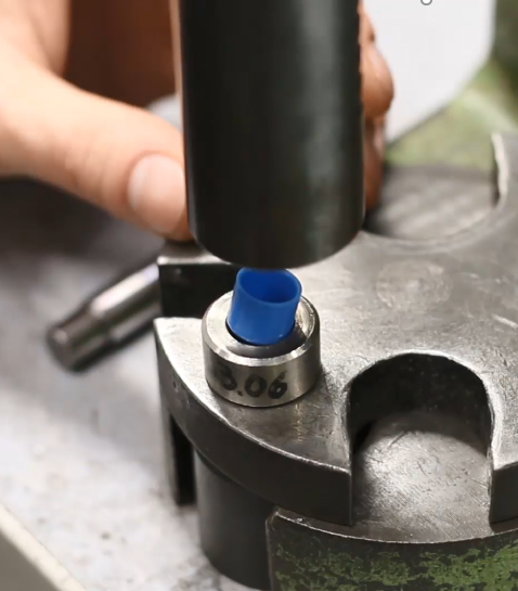
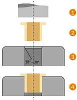
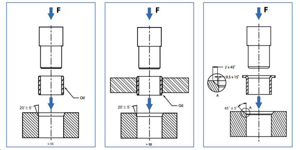
Assembly Methods Affect Results
How you install matters as much as what you install.
Mechanical press with flat punch: Most controlled method, distributes force evenly
Rubber mallet and wood block: Acceptable for low volumes, risk of uneven installation
Hydraulic press: Good for production, requires proper fixturing
Thermal assembly: Cooling the bushing (liquid nitrogen) or heating the housing reduces insertion force and risk of galling
Hammer (not recommended): Risks damaging both bushing and housing
Never use a centering or calibrating pin during installation—it can damage the bearing surface and create excessive clearance.
7. Real-World Application Examples
Example 1: Heavy Machinery Pivot Arm
Scenario: A bronze bushing supports a oscillating pivot arm in excavator linkage. Loads are high, motion is slow, and maintenance access is difficult.
Requirements:
Bushing must not spin in housing
Shaft must pivot freely under load
Contamination resistance needed
Long service life between overhauls
Solution:
Housing: 50 mm H7 (+0.025/0)
Bushing OD: 50 mm p6 (+0.042/+0.026)
Bushing ID after installation: ~40 mm H8 target
Shaft: 40 mm f7 (-0.025/-0.050)
The heavy interference (0.026-0.042 mm) prevents spinning even under shock loads. The generous shaft clearance accommodates misalignment and contamination while maintaining function.
Example 2: Precision Instrument Shaft
Scenario: A small instrument requires a shaft that rotates with minimal friction while maintaining precise radial position.
Requirements:
Very low running torque
Minimal radial play
Small size (6 mm shaft)
Consistent performance across temperature
Solution:
Housing: 10 mm H6 (+0.009/0) for tighter control
Bushing OD: 10 mm p6 (+0.015/+0.009)
Bushing ID after installation: ~6 mm target
Shaft: 6 mm g5 (-0.004/-0.009)
The tighter H6 housing and g5 shaft provide minimal running clearance (0.004-0.018 mm) while ensuring the bushing remains secure. The smaller tolerance grades reflect the precision requirements.
Example 3: High-Temperature Application
Scenario: An oven conveyor uses bushings near heat sources. Operating temperature reaches 200°C, while assembly happens at 20°C.
Requirements:
Must run freely at operating temperature
Must not loosen at room temperature
Different expansion rates between steel shaft and bronze bushing
Solution:
Calculate thermal expansion: Bronze expands more than steel
Increase cold clearance to maintain running fit at temperature
Maintain standard housing interference (H7/p6)
Select shaft tolerance one class looser (e7 instead of f7)
At 200°C, a 30 mm shaft/bushing combination might see the ID grow 0.03 mm more than the OD, effectively increasing clearance. Starting with tighter cold clearance ensures proper hot operation.
8. Common Tolerance Problems and Solutions
Problem: Bushing Spins in Housing
Symptoms: Polished housing bore, burred edges, overheating at housing interface
Causes:
Insufficient interference
Housing bore oversized or out-of-round
Loss of press-fit due to temperature cycling
Housing material too soft
Solutions:
Verify housing bore within H7 tolerance
Increase interference class (p6 → r6 → s6)
Add axial retention (staking, set screws, or flanges)
Consider different bushing material with higher modulus
For light alloy housings, increase interference to account for expansion
Problem: Shaft Seizes in Bushing
Symptoms: Unable to rotate, scoring on shaft, bushing ID damaged
Causes:
Insufficient running clearance
Thermal expansion closing gap
Contamination ingress
Lubrication failure
Misalignment
Solutions:
Verify shaft tolerance (f7 or g6, not h or j)
Increase clearance for high-temperature operation
Add lubrication features (grooves, pockets)
Check housing alignment
Consider self-lubricating materials like MYWAY graphite bushings
Problem: Excessive Noise or Vibration
Symptoms: Rattling, buzzing, or knocking during operation
Causes:
Excessive running clearance
Worn components
Housing resonance
Intermittent loading
Solutions:
Tighten shaft tolerance (g6 instead of f7)
Check for housing wear
Verify bushing length adequate for load
Consider dampening materials or designs
Problem: Short Service Life
Symptoms: Visible wear before expected life, frequent replacement needed
Causes:
Incorrect material for environment
Insufficient lubrication
Edge loading from misalignment
Abrasive contamination
Solutions:
Review material selection (MYWAY offers multiple bronze alloys for different conditions)
Add lubrication features or switch to self-lubricating design
Improve sealing
Check alignment and housing squareness
9. How MYWAY Achieves Precision Tolerances
Advanced CNC Manufacturing
At MYWAY, precision isn’t an afterthought—it’s built into every manufacturing step. Our CNC machining centers operate with tolerances measured in microns, not tenths.
Our capabilities:
5-axis, 4-axis, and 3-axis CNC machines for complex geometries
Tolerances as tight as ±0.005 mm for critical applications
CMM verification for every production run
Surface finishes optimized for each application
Every MYWAY bushing follows a digital thread from design to delivery. Your drawings become G-code that guides our machines through each cutting operation, eliminating the variation of manual processes.
Material Expertise
Different applications demand different materials. MYWAY stocks and machines multiple bronze alloys to match your operating conditions:
High-Strength Brass (CuZn25Al5): For mining and heavy equipment where impact loads dominate
Tin Bronze (CuSn10): For marine environments requiring corrosion resistance
Aluminum Bronze (CuAl10Fe5Ni5): For high-load, high-speed, or high-temperature applications
Lead Bronze (CuPb10Sn10): For power generation and steel mills where anti-friction properties matter
Each alloy responds differently to interference fits. Our engineers understand these nuances and can recommend the right material for your specific application.
Quality Systems That Deliver Consistency
Precision in one part is good. Precision in ten thousand parts is better. MYWAY’s IATF/ISO certification ensures that every part—whether prototype or production run—meets the same exacting standards.
Our quality approach:
Incoming material verification before cutting begins
In-process inspection at critical operations
Final CMM inspection with full reporting available
Traceability from raw material to finished part
When your drawing specifies H7/p6, MYWAY delivers it—every time.
Standard sizes match industry norms; custom designs match your unique requirements.
Tolerance Selection Checklist
Use this guide when specifying bushing fits:
Step 1: Define Operating Conditions
Load magnitude and direction
Speed (RPM or linear velocity)
Temperature range (minimum, maximum, operating)
Lubrication type and availability
Contamination exposure
Step 2: Select Housing Fit
Housing material (steel, cast iron, aluminum)
Housing bore tolerance: H7 (standard) or H6 (precision)
Required interference: p6 (light), r6 (medium), s6 (heavy)
Consider wall thickness effects on ID reduction
Step 3: Determine Running Clearance
Shaft tolerance: f7 (free running), g6 (close running), h6 (precision)
Account for thermal expansion differences
Include lubrication film requirements
Consider contamination tolerance needs
Step 4: Verify Post-Installation Dimensions
Calculate expected ID after press-fit
Specify inspection method (plug gauge, air gauge, CMM)
Define acceptance criteria
Step 5: Document Requirements
Call out standards used (ISO 286, ANSI B4.1)
Specify surface finish requirements
Include edge break and chamfer details
Note any special installation requirements
Frequently Asked Questions
Q: What does H7 tolerance mean?
A: H7 indicates a hole tolerance where the lower deviation is zero and the upper deviation follows the IT7 grade. For a 20 mm hole, H7 means the acceptable diameter ranges from 20.000 mm to 20.021 mm. H7 is the standard tolerance for housing bores in bushing applications.
Q: What’s the difference between f7 and g6 shaft tolerances?
A: Both provide clearance fits with H7 holes, but g6 is tighter. For a 20 mm shaft, f7 ranges from -0.020 to -0.041 mm (shaft smaller than nominal), while g6 ranges from -0.007 to -0.020 mm. Choose g6 for more precise positioning, f7 for freer running or when lubrication is marginal.
Q: How much interference do I need for a bushing?
A: Typical interference ranges from 0.01 mm to 0.05 mm for diameters under 50 mm, scaling with size. The exact amount depends on housing material, wall thickness, and operating temperature. ISO p6 provides light press, r6 medium, and s6 heavy press fits.
Q: Can I reuse a bushing after removal?
A: Generally no. Press-fit installation deforms the bushing permanently. Removing it changes dimensions further, and you can’t guarantee proper interference upon reinstallation. Replace bushings during maintenance—it’s cheaper than the alternative.
Q: How do I measure a press-fit bushing’s ID?
A: After installation, use a plug gauge (go/no-go) sized to the minimum and maximum acceptable ID. For more precise measurement, air gauging or small-bore indicators can read the actual diameter. Measure in multiple locations—bushings can distort if pressed unevenly.
Q: What if my housing bore is slightly oversize?
A: Minor oversize might be acceptable if you can select a bushing with larger OD. For significant deviation, you have options: bush the housing to restore nominal size, use anaerobic retaining compounds to fill gaps, or remachine the housing. MYWAY can provide custom-sized bushings to match your actual housing dimensions.
Q: Do plastic bushings need different tolerances?
A: Yes. Plastic bushings typically require more running clearance due to moisture absorption and higher thermal expansion. Housing interference follows similar principles but with lower press forces. Always follow the manufacturer’s recommendations for specific plastic materials.
Q: What’s the best shaft finish for bronze bushings?
A: For bronze bushings, shaft surface finish of 0.2 to 0.4 µm Ra works well—smooth enough to reduce friction but with enough “tooth” to retain lubricant. Hardened shafts (HRC 45-55) resist wear and maintain finish over time. MYWAY recommends 45# steel with HRC 42-52 for optimal performance.
Conclusion: Precision That Performs
Bushing tolerance of fit isn’t just about making parts that assemble—it’s about creating systems that perform reliably over time. The right fit prevents spinning, maintains lubrication, accommodates thermal changes, and delivers the service life your application demands.
From housing interference that locks the bushing in place to shaft clearances that enable smooth motion, every tolerance decision affects real-world performance. Understanding these relationships transforms bushing selection from guesswork into engineering.
At MYWAY, we’ve spent 20 years mastering these details. Our CNC-machined bushings hold tolerances that keep your equipment running—whether you need standard sizes for quick replacement or custom designs for unique applications.
Ready for bushings that fit right the first time? Contact MYWAY today with your requirements. Send us your drawings, your operating conditions, or your toughest challenges. We’ll deliver precision that performs.
100000+ Types of Bushings – Contact Us for Details