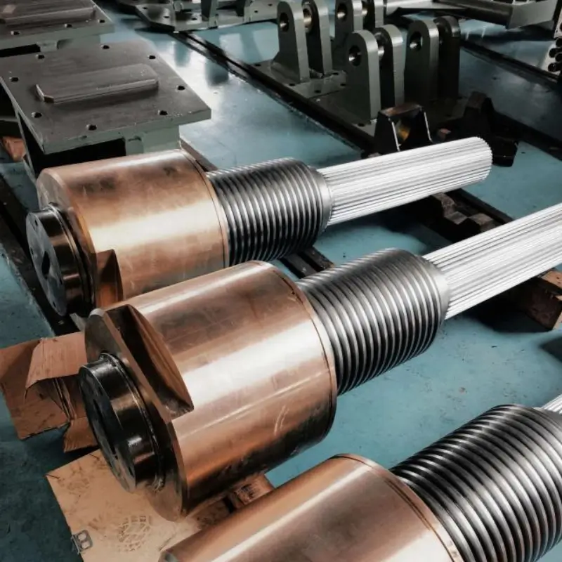
Ball Screw Nut 250×215×132×216×180.2
The workpiece is made of aluminum bronze ZCuAl10Fe3 with a scale of 1:4 and single piece weight of 55kg, its overall dimension specification is 250×215×132×216×180.2. The part is designed with stepped inner and outer circles, four Φ10 mounting through holes and 30° trapezoidal thread grooves on end face; geometric tolerances include multiple perpendicularity and coaxiality tolerances of 0.12. Technical requirements specify metal heat treatment and deburring treatment for the workpiece, threads shall be machined in accordance with standard GB/T13576-2008, and castings are forbidden to have sand holes, air holes and other defects.
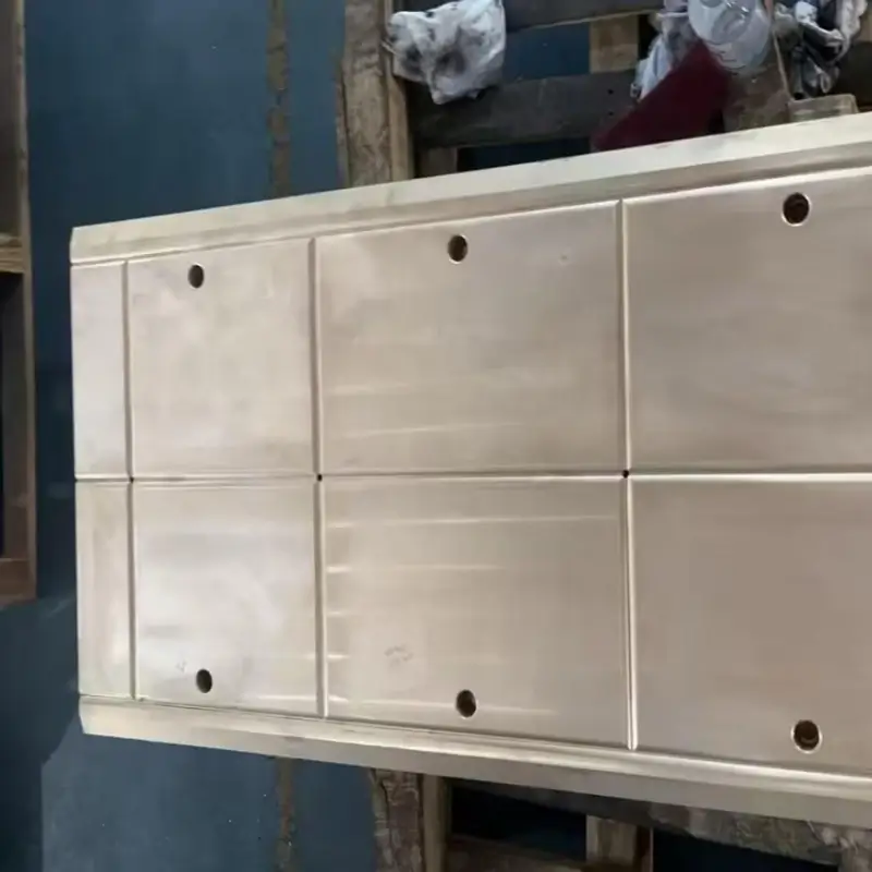
slide plate 1210×600×30
The component is made of tin bronze ZCuSn12Pb1, drawn at a scale of 1:6 with a single piece weight of 168kg. It is a rectangular plate part equipped with six mounting through holes on the surface, and its side edges are designed with 120° guiding inclined planes and stepped mounting grooves. Geometric tolerances including parallelism and symmetry are marked on the drawing, and the only technical requirement is edge chamfering.
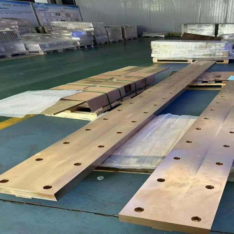
support slide plate 3622.6×250×88
It is made of tin bronze ZCuSn10P1, drawn at a scale of 1:6 with a single piece weight of 544kg. The part is a long strip plate with two rows of evenly distributed mounting holes on its surface and trapezoidal guide grooves on the cross-section. Multiple geometric tolerances of parallelism and perpendicularity are marked on the drawing. The technical requirements include edge chamfering, unmarked fillet radius R0.5 and unmarked 45° chamfers
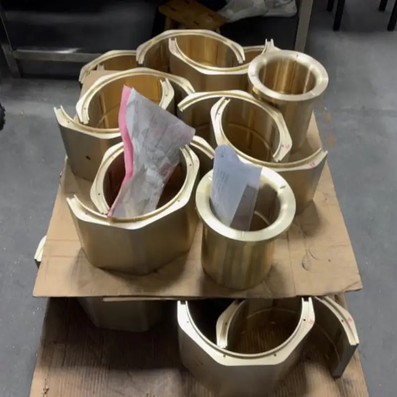
Bidirectional Clearance Sliding Sleeve 332.2×260×170
It adopts a split two-half bushing structure made of CuAl10Fe2-C-GM material. The nominal inner bore diameter of the part is Φ280 with an octagonal outer profile and a split parting line. Multiple sets of M8×15 threaded holes, oil grooves, 36°×10 lubrication grooves and transition fillets such as R30 and R45 are arranged on the workpiece. Cross-section views mark dimensional tolerances of inner diameter, wall thickness and assembly inclined planes. This component is assembled by two half sliding sleeves
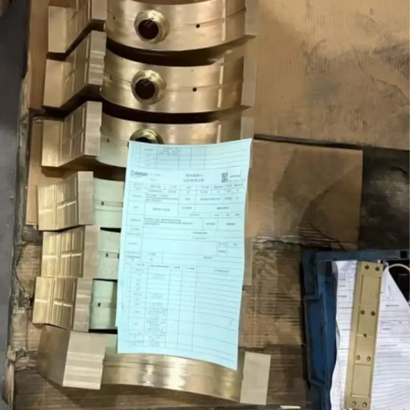
sliding block 290×185×75
The workpiece is a block component with an arc-shaped concave mating surface, internally equipped with multiple through oil grooves and mounting threaded holes on the side face. Multiple geometric tolerances including parallelism and symmetry are marked on the drawing, with full views of main drawing, cross-sections and partial enlarged details provided. The only technical requirement is edge chamfering
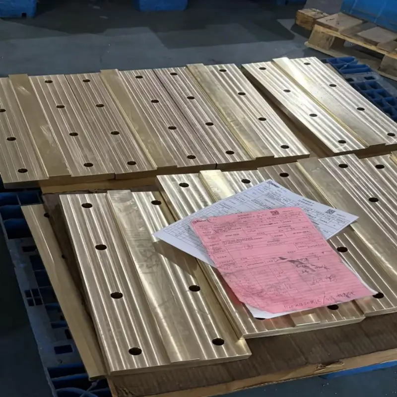
liner plate 500×200×46
it is made of copper alloy ZCuZn25Al6Fe3Mn3. The workpiece is a rectangular flat plate with eight mounting through holes evenly arranged in two rows on the surface and a M12×25 positioning threaded hole in the middle, and an arc matching groove is set on its cross section. Geometric tolerances such as flatness and symmetry are marked on the drawing. The technical requirements specify paired machining for two pieces, qualified fitting contact surfaces and qualified surface roughness
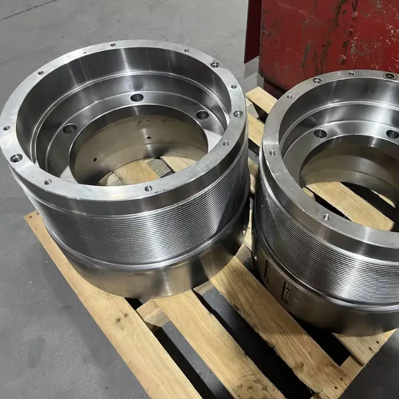
bearing bush 485×470×290×368.5×148.5
weighing 180kg per piece, which is made of alloy steel 40CrNiMoA. The workpiece is a stepped annular sleeve structure with multiple sets of M12 mounting threaded holes evenly distributed on the end face and multiple trapezoidal lubricating oil grooves inside the inner bore. Multiple section views mark geometric tolerances such as concentricity and perpendicularity as well as precise dimensional tolerances. The technical requirements cover casting flaw detection, deburring, thread machining and heat treatment in accordance with relevant standards
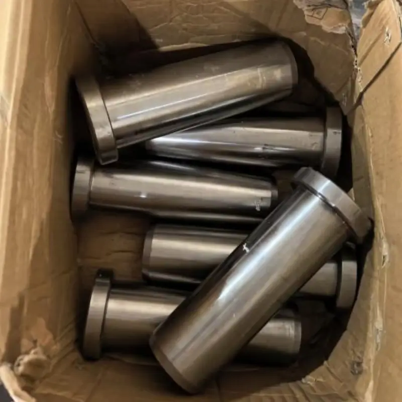
pin shaft 70×60×0×185×10
It is a stepped cylindrical pin shaft equipped with a Φ70 limiting boss at one end, an M10×1 threaded hole on the end face, a Φ60e8 tolerance fitted shaft body and a radial Φ8 oil hole on the side. Both ends are machined with 45° chamfers and R0.8 transition fillets. The technical requirements specify quenching and tempering treatment to achieve hardness of 217~255HBW and full edge chamfering
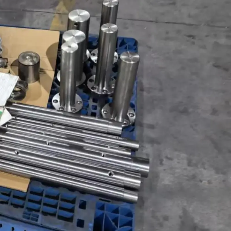
straight shaft
The workpiece adopts a stepped cylindrical shaft structure, with two sections of M2-M4 threads at one end, the basic outer diameter of the shaft body is Φ25, and both ends are machined with 1×45° chamfers and R0.5 transition fillets. The drawing marks the geometric tolerance of concentricity. The technical requirements require quenching and tempering treatment to reach hardness of 210~250HBW and blunting all sharp edges
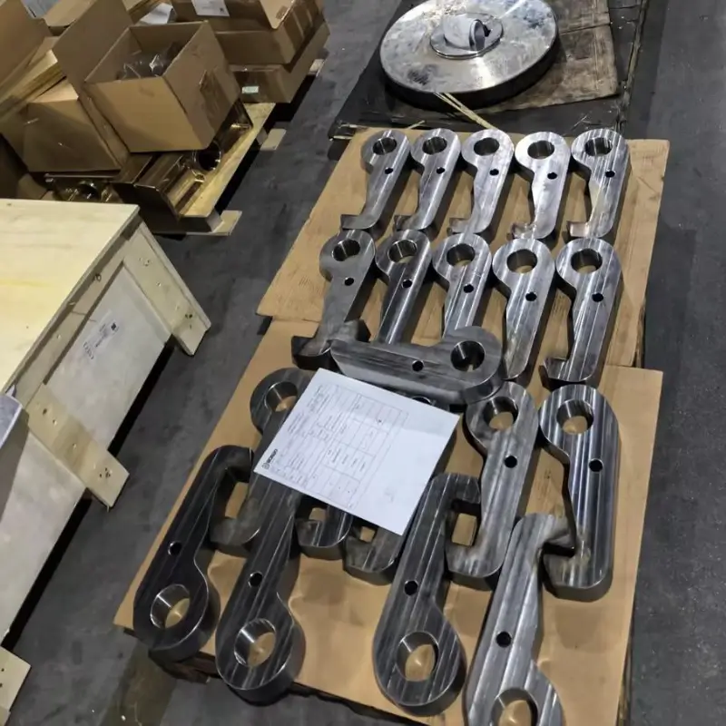
lifting hook 320×130×50
The workpiece is a bent special lifting lug structure with multiple transition fillets including R40, R60 and R5. It is equipped with a large Φ60 mounting hole at one end and a small Φ20 positioning hole in the middle, and the hook head is designed with a 30° bearing inclined plane and 1×45° chamfers. Cross-section view marks dimensional tolerances of thickness and hole diameters. The technical requirements require quenching and tempering to reach hardness of 217~255HBW, surface quenching of specified working surface with hardness HRC50~55 and hardening depth of 1~2mm, as well as chamfering of all edges
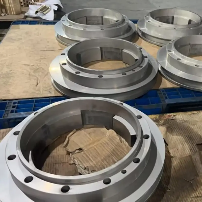
through cover 455×370×264×103.5×47.5
The cross-section view marks stepped wall thickness, inner and outer circle diameters as well as geometric tolerances including concentricity and flatness. The technical requirements specify quenching and tempering treatment to reach hardness of 250~280HBW, overall nitriding treatment with nitriding layer depth of 0.4mm and surface hardness of 500~700HV, unmarked 45° chamfers and unmarked fillet radius R0.8, and also clarify multiple manufacturing standards such as casting flaw detection, dimensional tolerance and thread machining.
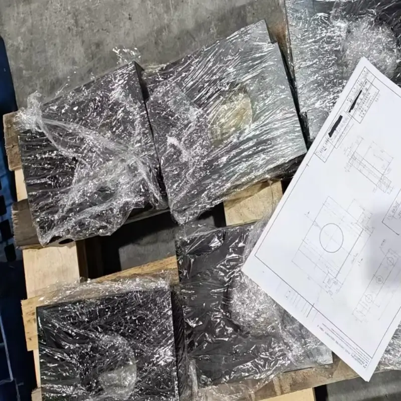
hinge lug 220×180×45
it is made of low-alloy structural steel Q355B. The workpiece is a rectangular plate-type hinge support, with a large Φ90.2 hinge hole in the center of the plate surface and two symmetric Φ26 mounting through holes on both sides, as well as an M10×1 threaded hole at the center of the end face. All corners are machined with 2×45° chamfers and R1 transition fillets, and flatness dimensional tolerances are marked on the drawing. The only technical requirement is edge chamfering and deburring
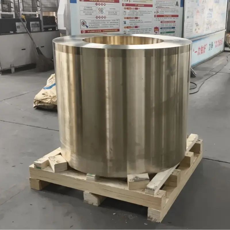
Screw-down Nut 1056×627×906
Large-size trapezoidal transmission threads are machined inside the workpiece, and multiple sets of mounting holes and lubricating oil passages are evenly distributed on the outer circumference. A full set of sectional and partial enlarged views are provided to mark precise dimensions and geometric tolerances including thread profile, wall thickness and hole diameter. Complete technical specifications are attached to the drawing, putting forward strict requirements for multiple manufacturing procedures such as heat treatment, flaw detection, thread machining accuracy and surface treatment.
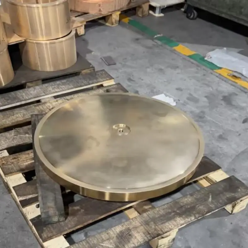
convex spherical washer 682×0×94
It is a circular gasket with a convex spherical surface of SR556.42 on one side and a flat surface on the other. Multiple radial oil grooves are distributed on the disc surface with a central mounting hole. The cross-section marks R32 transition radii and thickness dimensional tolerances. The technical requirements specify that the casting shall be free of sand holes, air holes and other defects, the fitting rate between spherical surface and matching plane shall not be less than 70%, production shall comply with corresponding bronze casting standards, and all sharp edges need chamfering.
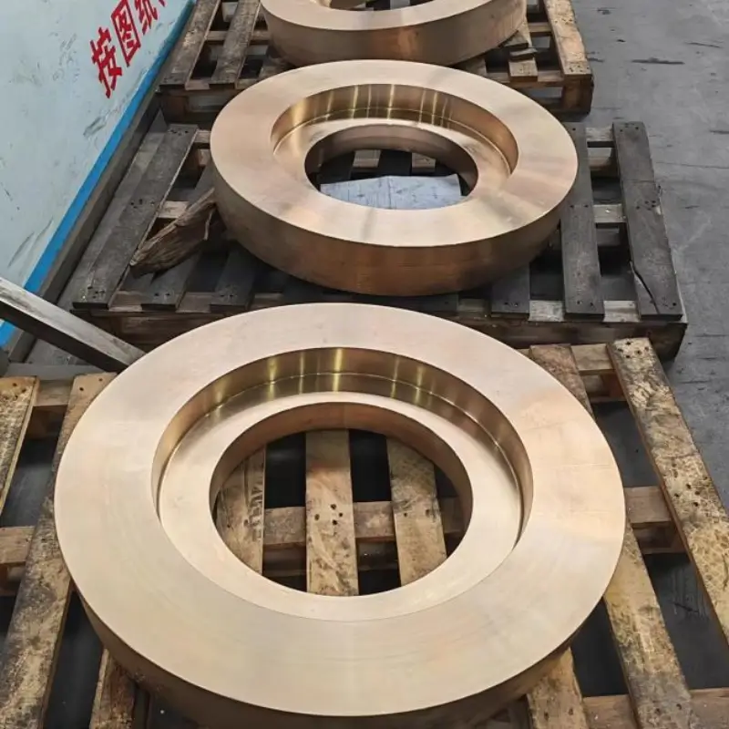
wheel rim 748×466×104
The workpiece is an annular stepped casting with marked dimensions including inner and outer circle diameters, thickness and R10 transition fillet. The technical requirements specify casting shall comply with JB/T 5000.5-2007, produced by centrifugal casting or metal mold casting, free of cracks, slag inclusions and other defects affecting strength, with hardness ≥HB100 and tensile strength ≥300N/mm². Mechanical test blocks shall be delivered together with the workpiece, and the gear tooth area after finish machining shall undergo Level 3 penetrant testing in accordance with JB/T9218-1999.

wheel rim 1572×1266×229
The workpiece is an annular stepped casting with key dimensions including inner and outer circle diameters, thickness, R10 and R5 transition fillets marked on the drawing. The technical requirements specify casting shall comply with GB/T37400.5-2019 and be produced by centrifugal casting or metal mold casting, free of cracks, slag inclusions and other strength-impairing defects. Ultrasonic testing of Level 2 per EZB554-2002 shall be carried out on areas with surface roughness Ra3.2 after rough machining. The material mechanical properties must meet hardness ≥HB100, tensile strength ≥300MPa, yield strength ≥180MPa and elongation ≥8% with attached test coupons.
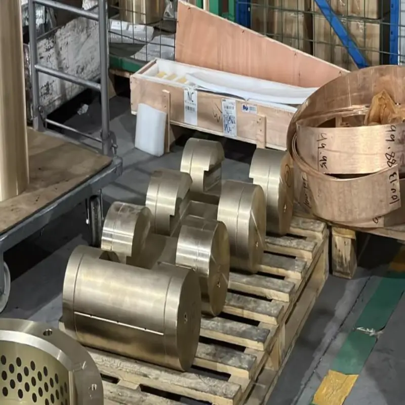
copper pin shaft 185×0×420
The workpiece is a stepped cylindrical copper pin shaft equipped with multiple fitted shaft diameters, 30° guide inclined planes and 3×45° chamfers at both ends. A G1/4 oil hole and spherical lubrication structure are arranged at the center. Cross-section views mark geometric tolerances such as concentricity and precise dimensional tolerances. The technical requirements specify the casting shall comply with GB/T37400.5-2019 and be free of casting defects including shrinkage porosity, cracks, air holes and slag inclusions. Burrs shall be removed and all sharp edges chamfered after machining
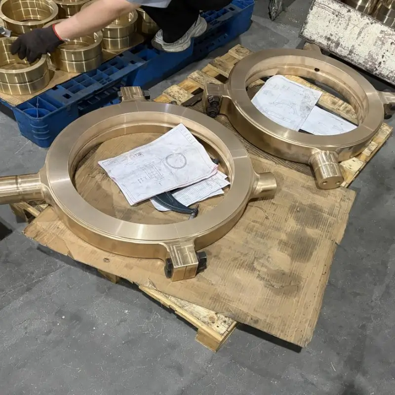
oil supply copper ring 710×397×100、710×330×100
It is an annular copper part with bilateral lugs, inside the ring there runs a through lubricating oil passage, and multiple groups of threaded mounting holes are arranged on the two side lugs. The drawing marks assembly torque, thickness of each section, inner and outer diameters and other structural dimensions. The technical requirement only states all sharp edges shall be polished smooth,and this copper component is used for assembly in the equipment lubrication system.
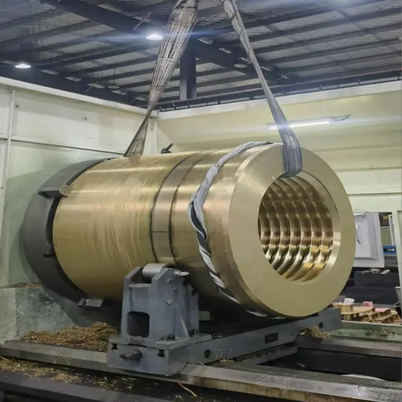
Screw-down Nut
Large-size trapezoidal transmission threads are machined in the inner bore, and multiple groups of threaded mounting holes as well as bilateral lubricating oil grooves are evenly distributed on the outer circumference. The drawing includes front view, full sectional view and multiple partial enlarged views, which clearly mark precise dimensions such as thread profile, wall thickness, hole diameter and geometric tolerances. Complete technical specifications are attached with strict manufacturing requirements for key processes including heat treatment, non-destructive testing, thread machining precision and surface quality.
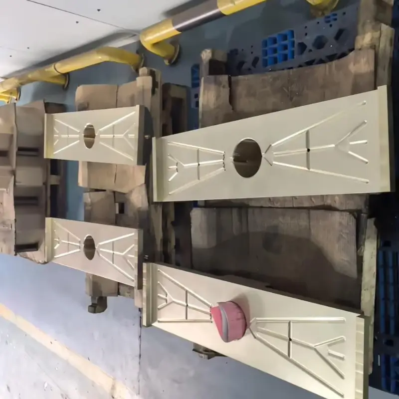
copper sliding block 1070×320×125
The workpiece is a long special-shaped sliding liner block with a large-diameter mounting through hole in the middle, a convex arc surface of SR658.8 machined on the sliding surface, multiple sets of cross oil storage ribs and arc lubricating oil grooves symmetrically distributed on the surface, and 30° guide inclined planes as well as transition fillets at both ends. The drawing marks dimensional tolerances of hole diameter, thickness, spherical radius and general dimensional tolerance standards, and production shall comply with the general technical conditions JB/T5000.
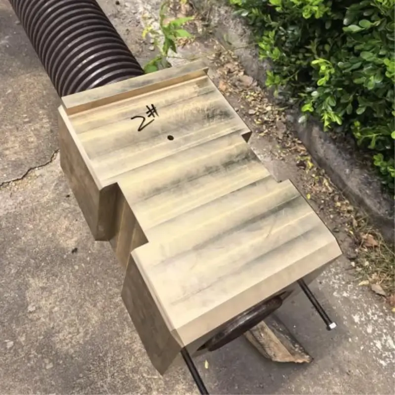
backup roll changing lead screw nut 403.11×158.8×393.7
The workpiece is a square sleeve with side lugs, four sets of M10 threaded holes with depth 30 are evenly distributed on the end face, trapezoidal transmission threads are machined in the inner bore, and the outer circle is marked with geometric tolerance of concentricity 0.03, with a Φ10 oil hole on the side and 2×45° chamfers on all end faces. The technical requirements require the casting to be free of pores, shrinkage cavities, slag inclusions and other defects, all unmarked edges shall be chamfered, and this part needs to be assembled with matching nuts, serving as a copper assembly component for mill roll changing system.
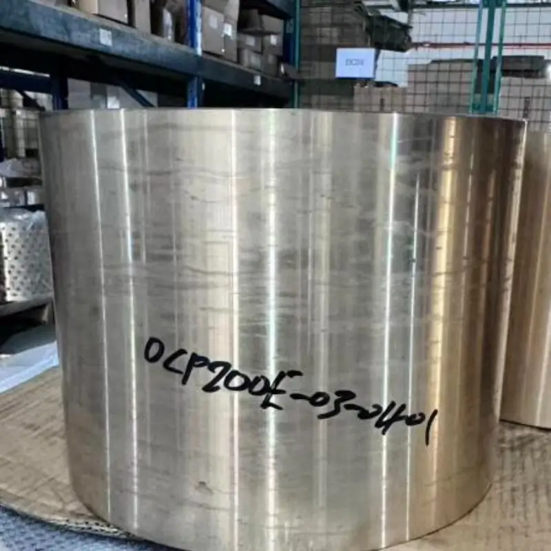
crank copper bush 270×249×205
The workpiece is an integral cylindrical sleeve with two annular oil grooves axially arranged on the barrel, two symmetric R45 oil groove positions with wire cutting allowance distributed on the circumference, and R4 & R2 transition fillets marked on the oil groove section. Precision dimensional tolerances are labeled for inner and outer circles, with R3 fillets and C1 chamfers on end faces. The process note specifies wire cutting first, tin welding followed by finish turning without splitting after machining. The technical requirements state unmarked chamfers are 0.5×45°, all sharp edges and burrs shall be removed, unmarked dimensional tolerances comply with GB/T1804-m, and unmarked geometric tolerances conform to GB/T1184-K. This copper sliding bush is matched for connecting rod mechanism assembly.
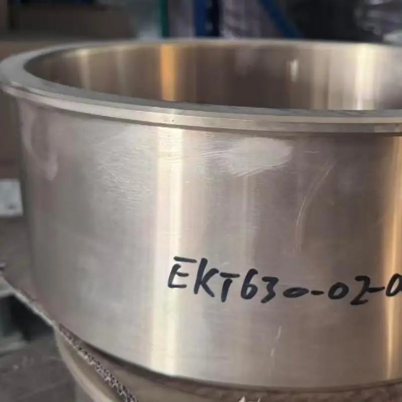
upper connecting rod bronze bush 360×345.2×319×130×8
The workpiece is a thin-walled cylindrical sleeve with an annular lubricating oil groove machined on the inner wall, and R4, R2 transition radii are marked on the partial enlarged view of the oil groove. Both ends of the barrel are equipped with R5 fillets, C2 chamfers and 30° guide inclined planes, and precise dimensional tolerances are labeled for inner and outer circles with surface roughness Ra3.2 for other surfaces. The technical requirements specify all sharp edges shall be blunted with burrs and flashes removed, no casting defects such as shrinkage porosity and air holes are allowed on inner and outer surfaces, unmarked geometric tolerances shall comply with GB/T1184-k, and unmarked machining dimensional tolerances shall follow GB/T1804-m. T
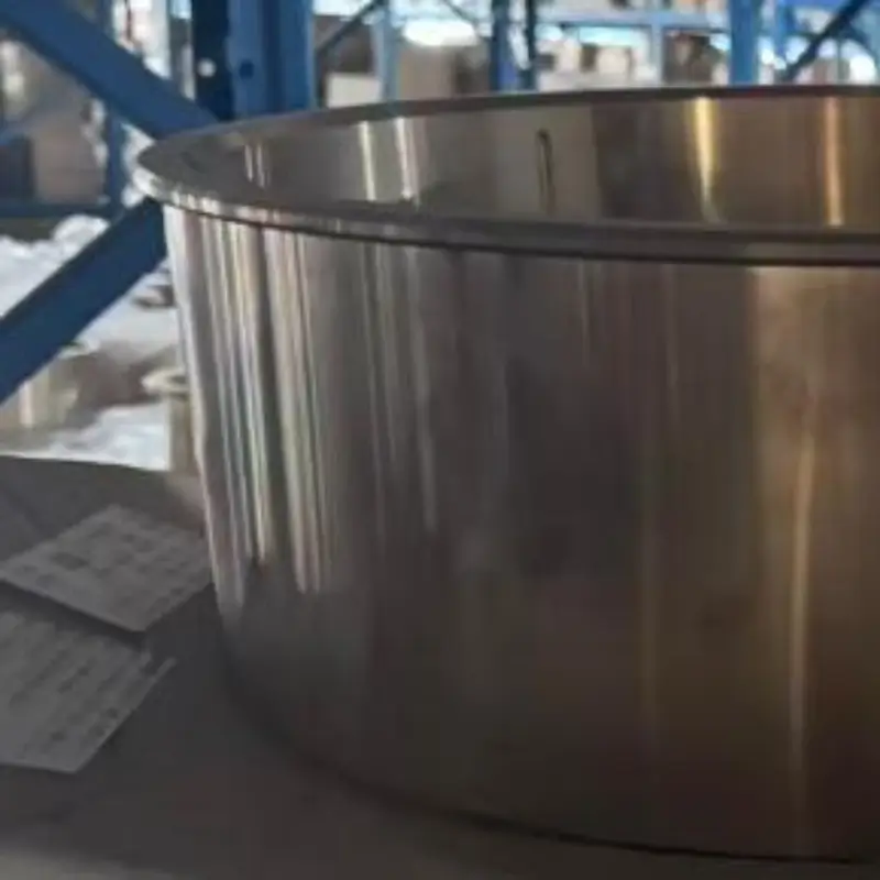
big-end bronze bush 545×530.5×504×166×8
The workpiece is a thin-walled cylindrical copper sleeve with two annular lubricating oil grooves on the inner wall, and R2, R4 transition radii are marked on the partial enlarged drawing of oil grooves. Four M8 threaded lifting holes with depth 15 are radially distributed on the barrel, the end faces are provided with C2 chamfers and two C5.5 notches, and the concentricity tolerance between inner and outer circles is 0.03. Precise dimensional tolerances of wall thickness, length and hole diameter are marked on the drawing. The technical requirements specify all sharp edges shall be blunted and burrs & flashes removed, casting defects such as shrinkage porosity and air holes are forbidden on inner and outer surfaces, unmarked geometric tolerances shall comply with GB/T1184-k, and unmarked machining dimensional tolerances shall follow GB/T1804-m
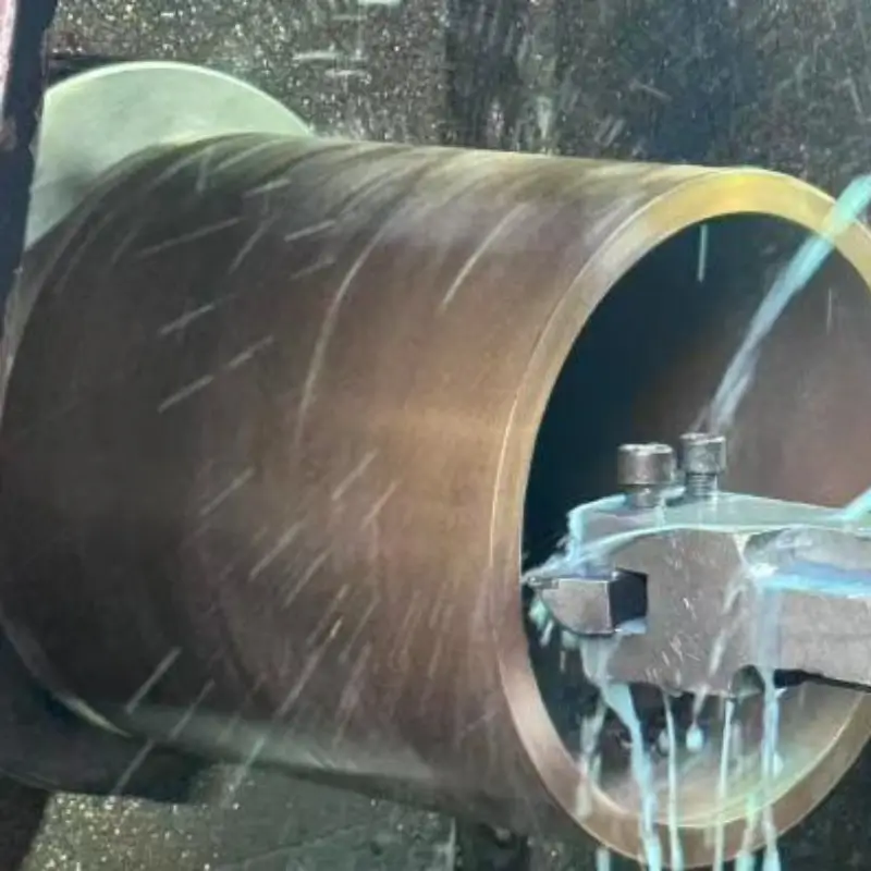
rear crankshaft bearing bush 300×269×220
The workpiece is a thin-walled cylindrical bearing bush with one annular lubricating oil groove on the inner wall, two symmetric R25 oil groove areas distributed on the circumference, and the dimension of the 60° oil storage groove is marked on the partial enlarged view of the oil groove. Both ends of the cylinder are equipped with 15° guide inclined planes and two C2.5 notches. Precise dimensional tolerances of inner and outer circles are marked on the drawing, with the concentricity tolerance between inner and outer circles of 0.02, and the surface roughness of other surfaces is Ra3.2. The technical requirements specify all sharp edges shall be blunted and burrs and flashes removed, casting defects such as shrinkage porosity and air holes are forbidden on inner and outer surfaces, unmarked geometric tolerances shall comply with GB/T1184-k, and unmarked machining dimensional tolerances shall follow GB/T1804-m.
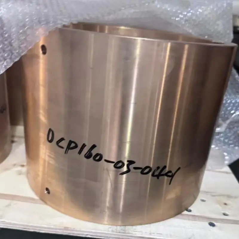
connecting rod bronze bush 250×224×190
The workpiece is an integral cylindrical copper liner with three annular lubricating oil grooves arranged axially on the barrel, two symmetric R45 oil groove machining positions with wire cutting allowance on the circumference, and R2 & R4 transition radii marked on the partial enlarged view of oil grooves. Precision dimensional tolerances are labeled for inner and outer circles, R3.5 fillets are arranged at both barrel ends, and unmarked chamfers are all 1×45°. The process requirement specifies wire cutting and tin welding before finish turning without splitting after processing. The technical requirements state all sharp edges shall be blunted and burrs removed, unmarked geometric tolerances comply with GB/T1184-k, and unmarked linear dimensional tolerances meet GB/T1804-m. This copper sliding bush is matched for connecting rod mechanism assembly.
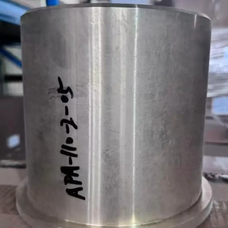
rear crankshaft bearing bush 180×160×144×160×10.5
One annular lubricating oil groove is machined on the inner wall, two symmetric R25 oil groove areas are arranged on the circumference, and the partial enlarged view of the oil groove shows a 15° oil storage structure. C3 chamfers, R1 and R15 transition fillets are set at both ends of the barrel. Precise dimensional tolerances of inner and outer circles as well as concentricity geometric tolerance of 0.02 are clearly marked, with surface roughness Ra1.6 on working surfaces. The technical requirements specify unmarked chamfers are all 1×45°, unmarked fillets R0.5, all sharp edges shall be blunted and burrs removed, unmarked dimensional tolerances comply with GB/T1804-m, and unmarked geometric tolerances meet GB/T1184-1996. This wear-resistant sliding liner is matched for the rear end of crankshaft.
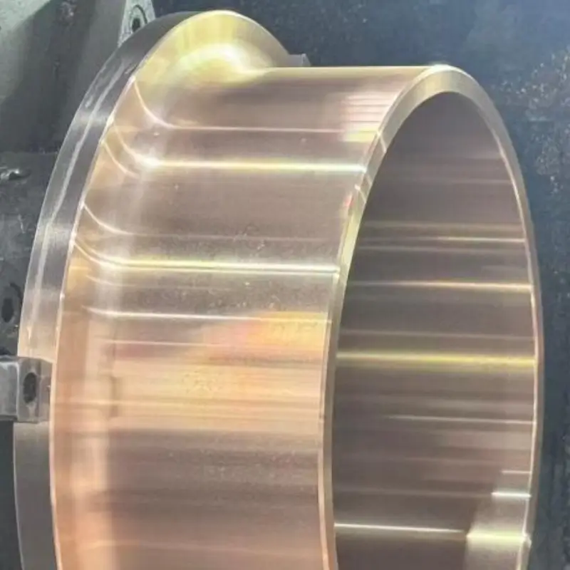
rear crankshaft copper bearing bush 445×430×399.4×138×10
Two annular lubricating oil grooves are machined on the inner wall, R3 and R4 transition radii together with 0.3mm machining allowance are marked on the partial enlarged drawing of oil grooves. 15° guide slopes, C4 chamfers as well as R1 and R4 transition fillets are arranged at both barrel ends. Precise dimensional tolerances of inner and outer circles are labeled, and the concentricity, end face parallelism and perpendicularity tolerances are specified as 0.02~0.03. The technical requirements state unmarked chamfers are all 1×45°, all sharp edges shall be blunted and burrs removed, unmarked dimensional tolerances comply with GB/T1804-m, and unmarked geometric tolerances meet GB/T1184-K. This copper bush serves as wear-resistant sliding support for the rear end of crankshaft.
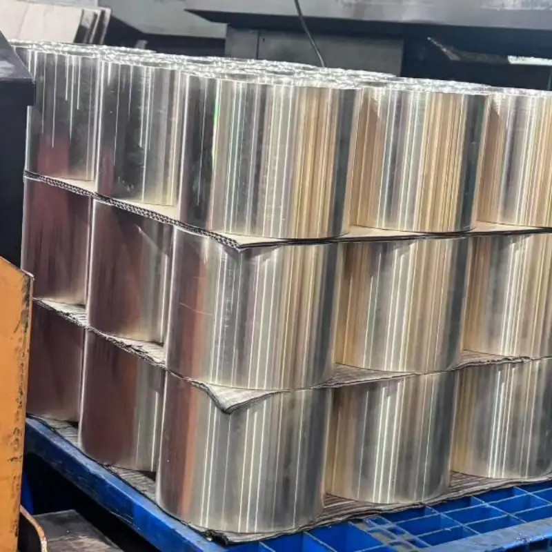
crank copper bush 150×129×120
Two annular lubricating oil grooves are machined on the inner wall, two symmetric R25.5 oil groove positions with wire cutting lines are arranged on the circumference, and a 30° oil storage structure is shown on the partial enlarged view of oil grooves. Both barrel ends are provided with R5.5 fillets and C0.5 chamfers, precise dimensional tolerances are marked for inner and outer circles, the roughness of working surfaces is Ra1.6 and Ra3.2 for other surfaces. The process note requires wire cutting and tin welding before finish turning without splitting after machining. The technical requirements specify unmarked chamfers are all 0.5×45°, all sharp edges shall be blunted with burrs removed, unmarked dimensional tolerances comply with GB/T1804-m, and unmarked geometric tolerances meet GB/T1184-1996. This wear-resistant copper liner is matched for crank mechanism assembly.
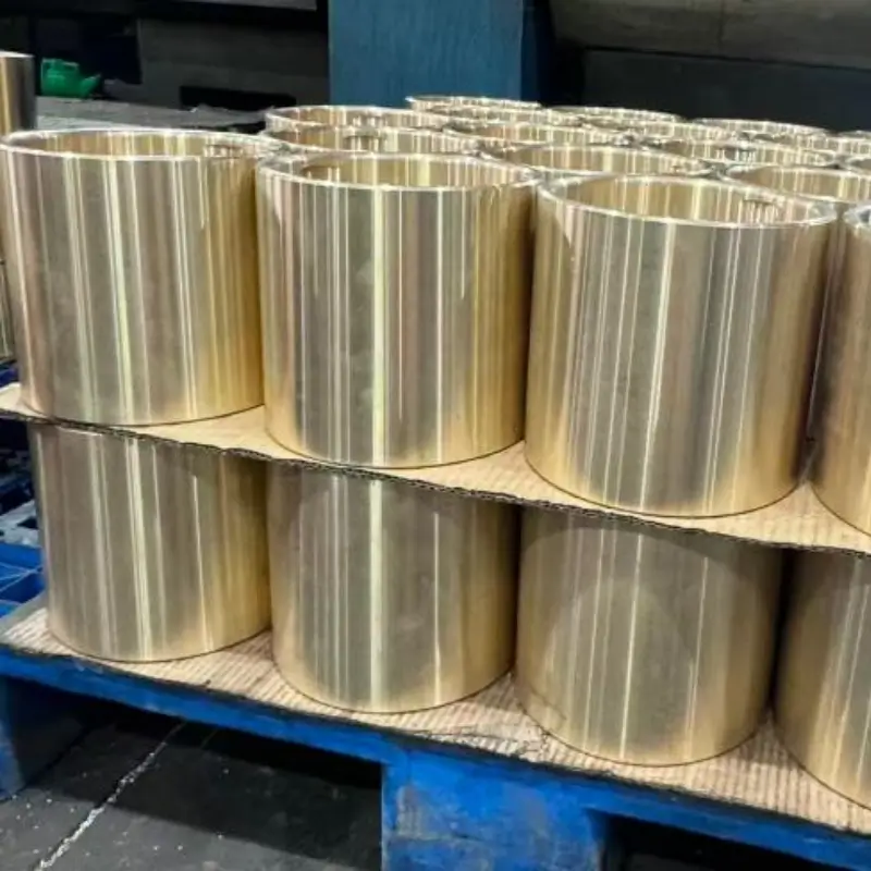
crank copper bush 180×159×170
Two annular lubricating oil grooves with 15° inclined surfaces are machined on the inner wall of the barrel. Two symmetric R30 oil groove zones with wire cutting reference lines are arranged on the circumference, and R5.5 transition fillets are provided at both ends of the barrel. Precision dimensional tolerances are marked for inner and outer circles, the surface roughness of working surfaces is Ra1.6, and Ra3.2 for other surfaces. The process note requires wire cutting and tin welding before finish turning without splitting after machining. The technical requirements specify all unmarked chamfers are 2×45°, all sharp edges shall be blunted, unmarked geometric tolerances comply with GB/T1184-1996, and unmarked dimensional tolerances meet GB/T4249-2009. This wear-resistant copper liner is used for the assembly of crank mechanism.
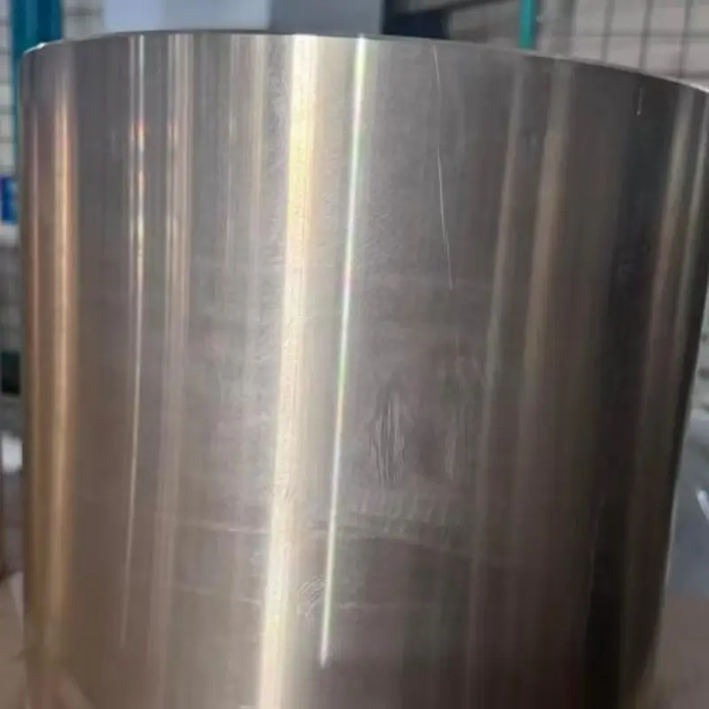
crank copper bush 265×239×245
Two symmetric R45 oil groove machining positions with wire cutting reference lines are distributed on the circumference, and R5 fillets as well as 15° guide inclined planes are set at both ends of the barrel. Precise dimensional tolerances are labeled for inner and outer circles, the roughness of sliding working surfaces is Ra1.6 and Ra3.2 for other surfaces. The process note specifies wire cutting and tin welding shall be carried out prior to finish turning without splitting after machining. The technical requirements state all unmarked chamfers are 0.5×45°, all sharp edges shall be blunted and burrs removed, unmarked dimensional tolerances comply with GB/T1804-m, and unmarked geometric tolerances meet GB/T1184-K. This wear-resistant copper liner is matched for crank mechanism assembly.
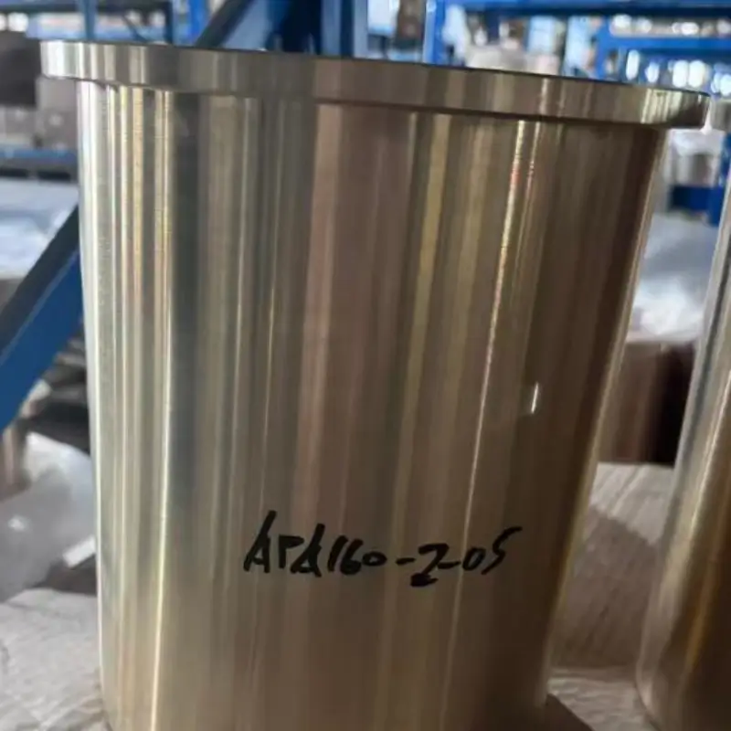
rear crankshaft bearing bush 220×200×179×255×10.3
One annular lubricating oil groove is machined on the inner wall, two symmetric R25 oil groove structures and assembly notches are distributed on the circumference, and the 15° oil storage groove dimension is shown on the partial enlarged view of oil grooves. R1, R15 transition fillets, C1.5 chamfers and 15° guide slopes are arranged at both ends of the barrel. Precise dimensional tolerances of inner and outer circles are marked, the surface roughness of working surfaces is Ra1.6 and Ra3.2 for other surfaces. The technical requirements specify all unmarked chamfers are 1×45°, all sharp edges shall be blunted, unmarked geometric tolerances comply with GB/T1184-1996, and unmarked dimensional tolerances meet GB/T4249-2009
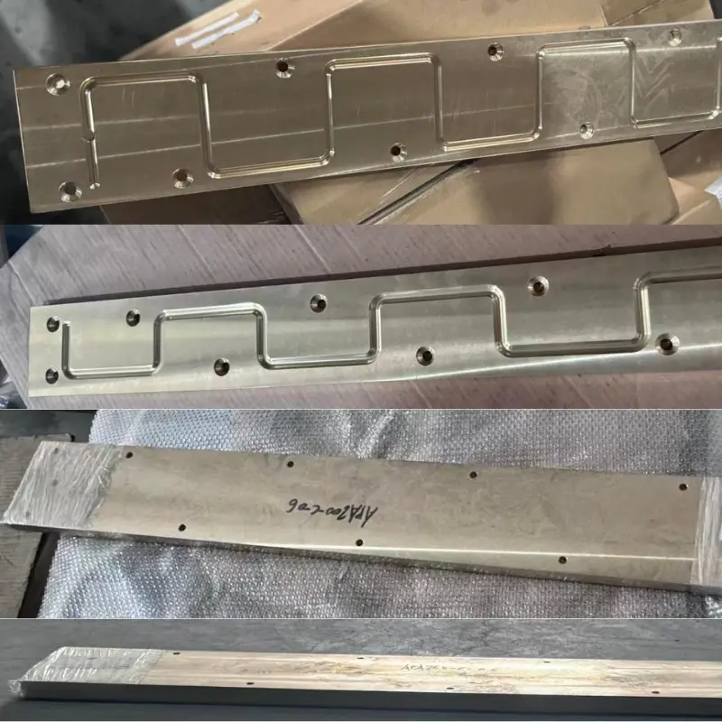
copper sliding block (copper plate)1003×65×10.5, 1003×130×10.5, 1003×68×10.5 and 1003×145×10.5.
The workpiece is a long thin copper plate with multiple parallel oil storage grooves machined on the sliding surface, and multiple groups of Φ9 through fixing holes evenly arranged along the length of the plate. The detailed drawing of fixing holes shows a 90° counterbore structure, R2 transition radii are marked on the oil groove section, C8 chamfers are provided at plate ends, the surface roughness of sliding working face is Ra0.6 and Ra3.2 for other surfaces. The technical requirements state all unmarked chamfers are 0.5×45°, the marked inner diameter is the dimension before pressing plate, and Loctite 242 thread locker shall be applied to screws during assembly and fixing. This wear-resistant copper liner plate serves as sliding support for equipment.

crank copper bush 315×289×290
This drawing shows a crank copper bush with overall dimension specification of 315×289×290, drawn at a scale of 1:3.5, which is a cylindrical tin bronze sliding liner. Two annular lubricating oil grooves are machined on the inner wall of the barrel, two symmetric R45 oil groove zones with wire cutting reference lines are arranged on the circumference, and a 15° oil storage structure is marked on the partial enlarged view of oil grooves. R7 fillets and C2 chamfers are provided at both barrel ends, precise machining dimensional tolerances are labeled for inner and outer circles, the roughness of sliding working surfaces is Ra1.6 and Ra3.2 for other surfaces. The process note specifies wire cutting and tin welding before finish turning without splitting after machining. The technical requirements state all sharp edges shall be blunted with burrs removed, casting defects such as sand holes, shrinkage cavities and collision marks are forbidden on the surface, unmarked dimensional tolerances comply with GB/T1804-m, and unmarked geometric tolerances meet GB/T1184-1996. This wear-resistant copper liner is matched for crank mechanism assembly.
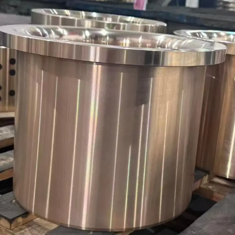
rear crankshaft bearing bush 340×290×259×250×20
This drawing shows rear crankshaft bearing bush with dimension specification of 340×290×259×250×20, drawn at a scale of 1:3.7, which is a cylindrical copper sliding liner. One annular lubricating oil groove is machined on the inner wall, 15° oil storage structure and R2 transition fillets are marked on the partial enlarged view of oil grooves, and two symmetric R25 oil groove areas are distributed on the circumference. R1, R22 transition fillets, C1 chamfers and 15° guide inclined planes are arranged at both barrel ends. Precision dimensional tolerances are labeled for inner and outer circles, the surface roughness of sliding working surfaces is Ra1.6 and Ra3.2 for other surfaces. The technical requirements specify all unmarked chamfers are 0.5×45°, all sharp edges shall be blunted and burrs removed, unmarked dimensional tolerances comply with GB/T1804-m, and unmarked geometric tolerances meet GB/T1184-1996. This wear-resistant sliding liner is matched for the rear end of crankshaft.
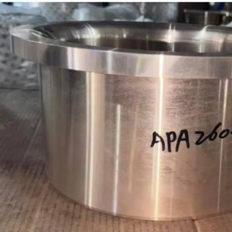
front crankshaft bearing bush 340×290×259×180×20
This drawing shows front crankshaft bearing bush with overall dimension specification of 340×290×259×180×20, drawn at a scale of 1:3.5, which is a thin-walled cylindrical copper sliding liner. One annular lubricating oil groove is machined on the inner wall, and a 15° oil storage structure is marked on the partial enlarged view of oil grooves, with two symmetric R25 oil groove areas arranged on the circumference. R2, R22 transition fillets, C1 chamfers and 15° guide inclined planes are set at both barrel ends. Precise dimensional tolerances of inner and outer circles are labeled, the surface roughness of sliding working surfaces is Ra1.6 and Ra3.2 for other surfaces. The technical requirements specify all unmarked chamfers are 0.5×45°, all sharp edges shall be blunted and burrs removed, unmarked dimensional tolerances comply with GB/T1804-m, and unmarked geometric tolerances meet GB/T1184-1996. This wear-resistant sliding liner is matched for the front end of crankshaft.