Why Excavator Linkage Bushings Wear Out Early and How to Prevent Repeat Failures
By MYWAY | September 22, 2026
If an excavator linkage becomes loose soon after a repair, check what caused the wear before fitting another bushing. Dirt, poor lubrication, excessive loading and incorrect fit can damage the replacement too. This guide explains how to inspect boom, arm and bucket pivots and choose a replacement that suits the job.
Start with the joint and its service history
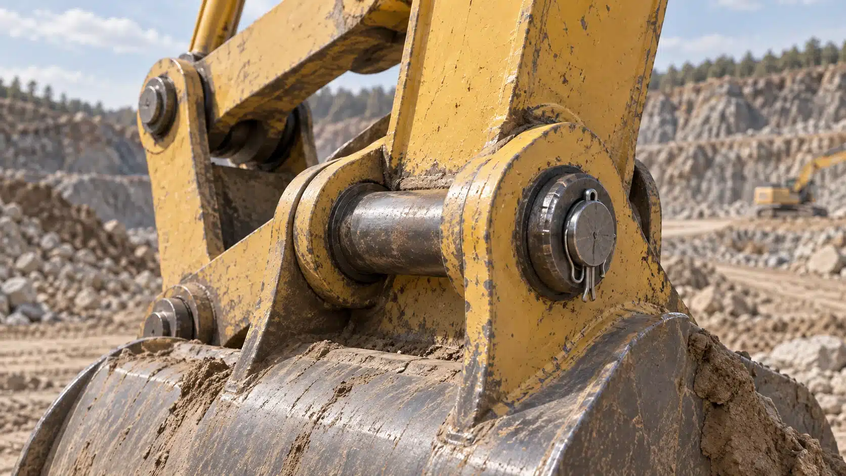
A bushing supports the pin through a sliding contact. Its performance depends on the surfaces it touches, the structure supporting it and the environment around it. An isolated photograph of a worn sleeve provides only part of that information.
Begin by identifying the exact pivot position and the machine configuration. Record the attachment, operating hours since installation, usual work, lubrication arrangement and point at which the operator first noticed a change. A bucket connection used for repetitive loading may experience a different duty from a joint on a machine doing demolition or working in abrasive slurry. Engine hours alone cannot describe those differences.
Preserve the evidence before cleaning everything. Photograph the bushing in its installed orientation, mark the main load direction if known, and keep the matching pin and seals with it. GGB’s failure-analysis guidance recommends collecting the associated components, lubricant, wear debris and actual operating data. .
Then build a short timeline. Was the joint tight immediately after assembly? Did noise appear after a change of attachment? Was a grease line replaced shortly before the failure? Has the same side of the machine needed repeated repairs?
These questions help organize an investigation. They do not establish causation on their own. A recent maintenance event may be relevant, or it may simply be the last event anyone remembers. Keep observations separate from explanations until measurements support the diagnosis.
Define what “early” means in the report as well. It may mean failure before an agreed acceptance point, a shorter interval than comparable joints under similar work, or an unexpectedly rapid change in measured clearance. Those are different claims. A statement that a bushing should last several years is difficult to assess without operating hours, workload and a wear limit. For a fleet comparison, choose machines with reasonably similar duties and identify the differences that remain. This gives the maintenance team a baseline it can revisit when the next inspection is due.
Abrasive contamination can turn normal movement into rapid wear
An excavator joint works close to soil, crushed rock and water. If hard particles reach the contact between the pin and bushing, they can scratch the surfaces and contribute to further wear. Damage can then increase the space available for contamination, allowing the process to continue.
The amount of mud visible outside the joint is a poor measure of what has reached the bearing surface. A dirty exterior may surround a well-protected connection. A comparatively clean assembly can still contain abrasive particles introduced through a damaged seal or during installation.
Inspect the contamination path. Look at seal condition, the surfaces on which the seals run, joint end protection and the cleanliness of grease fittings. Check whether the installation procedure allowed grit to enter an open bore. If the machine works in water, document the exposure rather than describing the application simply as outdoor service.
SKF’s composite-bearing guidance recommends external sealing where contamination is heavy. The important implication for an excavator is that a material described as self-lubricating still needs an appropriate approach to contamination control.
For a joint designed to receive grease, lubrication can also help remove contaminants. Caterpillar explains this function in its linkage-pin maintenance guidance and directs owners to the machine’s Operation and Maintenance Manual for locations and intervals. .
A practical repair record should therefore connect the surface damage with a plausible entry route. “Scored bushing” describes the result. “Damaged outer seal, scoring concentrated near that end, and abrasive debris inside the joint” gives the next investigation a much stronger starting point.
Shock loads and short oscillations need separate attention
Excavator linkages combine substantial forces with reversing movement. GGB identifies heavy loads, shock, vibration and harsh environmental exposure as central challenges in construction equipment. Those conditions explain why a material recommendation needs more detail than machine size and bushing diameter.
The force acting on one bushing is not automatically equal to the excavator’s published bucket digging force. Linkage geometry, cylinder forces and the way the joint shares load determine the reaction at that bearing position. The force may also change through the stroke.
A useful first calculation for a cylindrical bushing is its nominal projected bearing pressure:
p = F / (d × L)
Here, F is the radial load assigned to that bushing in newtons, d is the nominal bearing diameter in millimetres, and L is the bearing length in millimetres. The result is N/mm², equivalent to MPa. GGB uses projected area for this calculation and distinguishes maximum loading from the loading used in a life assessment.
Consider an illustrative calculation, using assumed values rather than data from a particular excavator. A bushing with a 60 mm diameter and an 80 mm length supports 96,000 N of radial load:
p = 96,000 / (60 × 80) = 20 MPa
If the assigned load briefly reaches 192,000 N, the same calculation gives 40 MPa. The doubling is an assumption chosen to show the effect of load. It is not a recommended shock factor or a measurement from field service.
Neither result captures local stress caused by a bent pin, a tilted bore or incomplete support. The calculation is a screening step. A final assessment must examine the actual contact conditions and the limits of the selected bearing system.
Movement deserves the same care. For an oscillation of ±15 degrees, one complete out-and-back cycle covers 60 degrees of angular travel. On the assumed 60 mm diameter, that is about 31.4 mm of sliding distance. At 20 complete cycles per minute, the average sliding speed is approximately 0.0105 m/s. These values follow the oscillating-motion relationship in GGB’s design guidance.
Using the assumed 20 MPa pressure gives an average pV of approximately 0.21 MPa·m/s. That number is not an approval criterion by itself. It does not describe peak sliding speed within the cycle, dwell time or the distribution of contact across the surface. Reversing motion repeatedly returns to the same portion of the joint, and an average can hide the conditions that govern wear.
Verify that lubrication reaches the working surfaces
A completed greasing entry is evidence that a maintenance task was recorded. It does not demonstrate that lubricant reached every intended contact.
For a grease-lubricated assembly, investigate the entire delivery path. Depending on the design, relevant checks include the fitting, passage alignment, grease grooves, remote lines and metering components. A blocked passage or damaged line can leave a local problem even when the rest of the machine receives normal service.
Keep the manufacturer’s procedure in view. Caterpillar specifically includes checks of grease fittings and, where fitted, autolube lines in linkage inspection. Its instructions also describe preparing the machine before inspection, including lowering implements and shutting down. Follow the relevant machine procedure whenever a joint must be inspected or serviced.
Avoid assigning one lubrication interval to all excavators or all pivots. Record the manual revision, the relevant service point and any instructions for severe operating conditions. A maintenance plan becomes easier to audit when it identifies the exact point instead of saying “grease machine.”
Access is an engineering and maintenance question worth separating from material selection. If a fitting is difficult to reach, possible responses include reviewing access, using an approved remote lubrication arrangement or evaluating a different bearing system. Difficulty reaching a joint does not prove that its current bushing can operate without grease.
The same discipline applies when changing to a self-lubricating product. Establish whether the selected grade is intended to run dry, requires assembly lubrication or permits periodic lubrication. Give that instruction to the maintenance team in writing. Otherwise, a new material can arrive with the old maintenance assumptions still attached to it.
Installed clearance and alignment can undo a good material choice
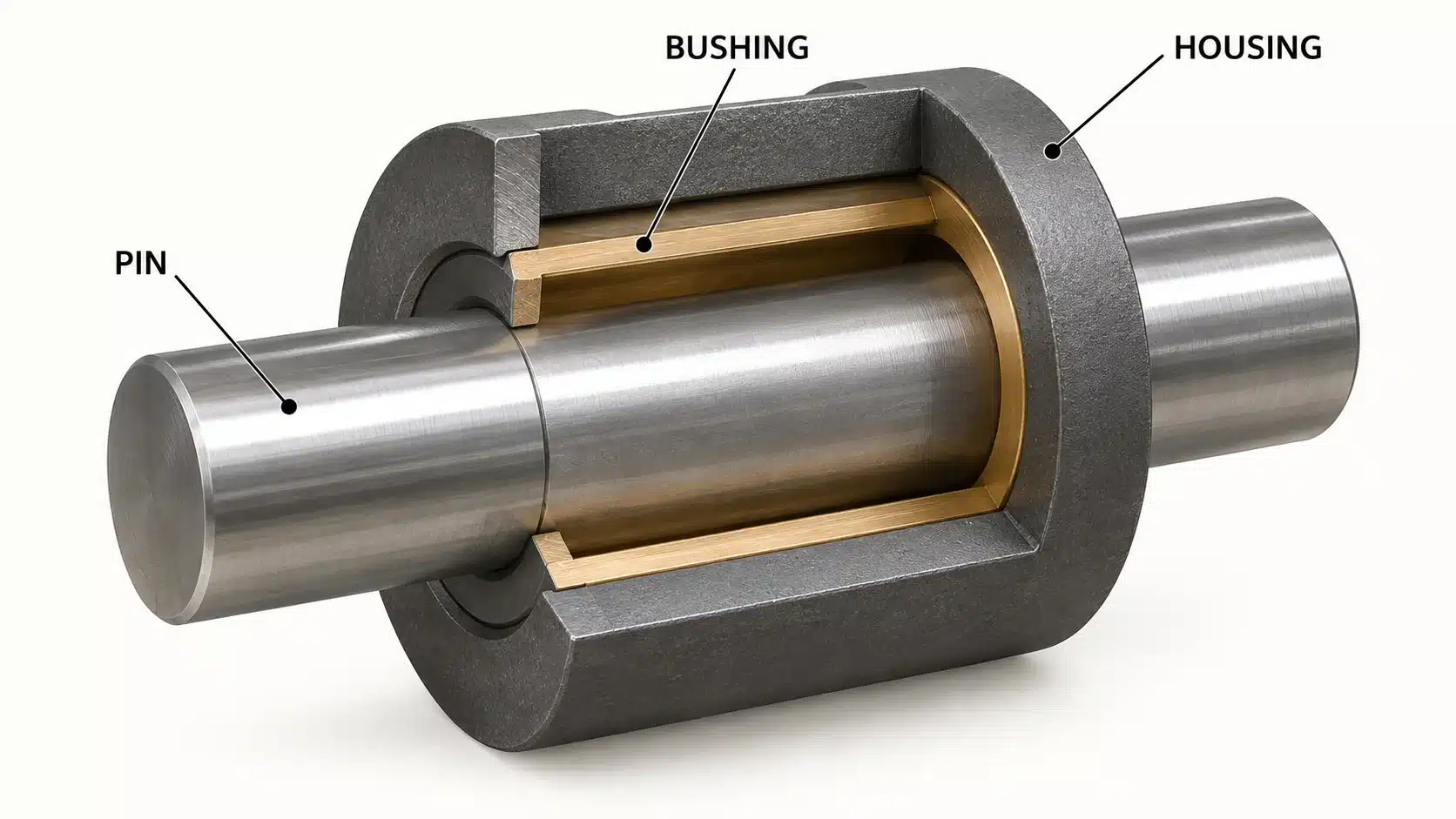
Dimensions on a loose bushing do not tell the whole story of its fit in service. Pressing it into a housing changes its condition. GGB distinguishes free-state dimensions from installed bore dimensions and explains that the installed bore governs clearance with the shaft. Wrapped bushings also require measurement methods suited to their split construction
For a repair shop, this means the inspection should include the housing, the installed bushing and the pin. Checking one of those parts while assuming the other two are correct leaves an avoidable gap.
As a practical inspection approach, measure the housing in more than one direction and at more than one axial position. Record the findings against the drawing or repair limits. Check the alignment between supporting bores where the joint uses more than one bearing position. If a bore requires repair, the decision should come from that dimensional assessment and the approved repair procedure.
Installation deserves its own record. GGB’s press-fit guidance identifies the mandrel, housing support and alignment, and control of installation force direction as important elements of the process.
A useful workshop checkpoint is to compare three states: housing before installation, bushing after installation and completed assembly. This helps distinguish a supplied-part issue from an installation or housing problem without relying on memory.
Also ask whether machining the installed bearing surface is permitted. Different constructions allow different finishing operations. A thin functional lining cannot be treated as though it were an unrestricted machining allowance. Obtain the specific product’s instructions before correcting a tight fit by removing material.
Evaluate the pin as carefully as the bushing
A replacement bushing will run against the existing pin unless the repair changes it. That makes pin condition part of the material decision.
Check diameter, wear pattern and surface condition against the applicable specification. When hardness or surface finish is a requirement, ask for the measurement rather than judging by appearance. A bright surface can still have the wrong dimensions or texture for the selected bearing.
igus explains that shaft material, hardness and surface roughness influence the performance of its polymer bushings. Its guidance is specific to those material pairings, but it reinforces the need to assess the pin and bushing together. Do not transfer an optimum roughness value from one product family to another.
Corrosion also deserves attention. igus describes how shaft corrosion can increase roughness and release particles that contribute to abrasion. If a joint repeatedly returns with a corroded pin, document moisture exposure and storage conditions as part of the investigation.
Reusing a pin should be a measured decision. Record why it passes the specified limits. If the inspection result is uncertain, that uncertainty belongs in the repair decision, not in an assumption that the new bushing will accommodate it.
Choose the bearing construction after defining the duty
There is no single material name that settles an excavator linkage application. The same machine contains different pivot positions, and a replacement must satisfy the requirements of the particular joint.
The following comparison is a starting point for a technical discussion. It is not a ranking or a list of interchangeable replacements.
| Bearing construction | What to establish before selection |
|---|---|
| Hardened steel bushing | Specified steel and heat treatment, matching pin condition, fit, lubrication and sealing requirements |
| Solid bronze or another copper-alloy bushing | Exact alloy, allowable duty, pin pairing, lubrication arrangement and dimensional requirements |
| Steel-backed bimetal bushing | Bearing-layer composition and thickness, backing support, lubrication and installation requirements |
| PTFE metal-polymer bushing | Exact lining formulation, load and motion limits, pin finish, installed clearance and contamination protection |
| Copper-alloy bushing with embedded solid lubricant | Base alloy, lubricant formulation, plug arrangement, motion requirements and dry or lubricated operating limits |
PTFE metal-polymer bearings combine a load-supporting structure with a low-friction sliding layer. GGB’s DU product explanation describes one specific construction, including a metal backing and a porous bronze interlayer containing a PTFE mixture. That description belongs to the identified product. A similar-looking sleeve or an SF-1 label is not, by itself, proof of identical composition or performance.
Embedded-solid-lubricant bearings also need precise identification. Oiles describes its 500SP1 series as a high-strength brass alloy with embedded solid lubricants and identifies suitability for high-load, low-speed conditions. This is a useful reminder that products casually grouped as “graphite bronze” can have different base alloys and lubricant systems.
For a purchasing specification, replace broad labels with questions the supplier can answer. Which exact grade is being offered? Under what lubrication condition was its data obtained? What pin finish and housing tolerance does it require? What test supports its use at the intended oscillation angle and load?
Manufacturer test results also need context. A controlled oscillation test can help compare materials under its stated conditions. It cannot establish the service life of a different excavator joint exposed to a different load history and contamination. Oiles publishes operating conditions alongside its 500SP1 test data, illustrating why the conditions should travel with the result
Use the wear pattern to decide what to investigate next
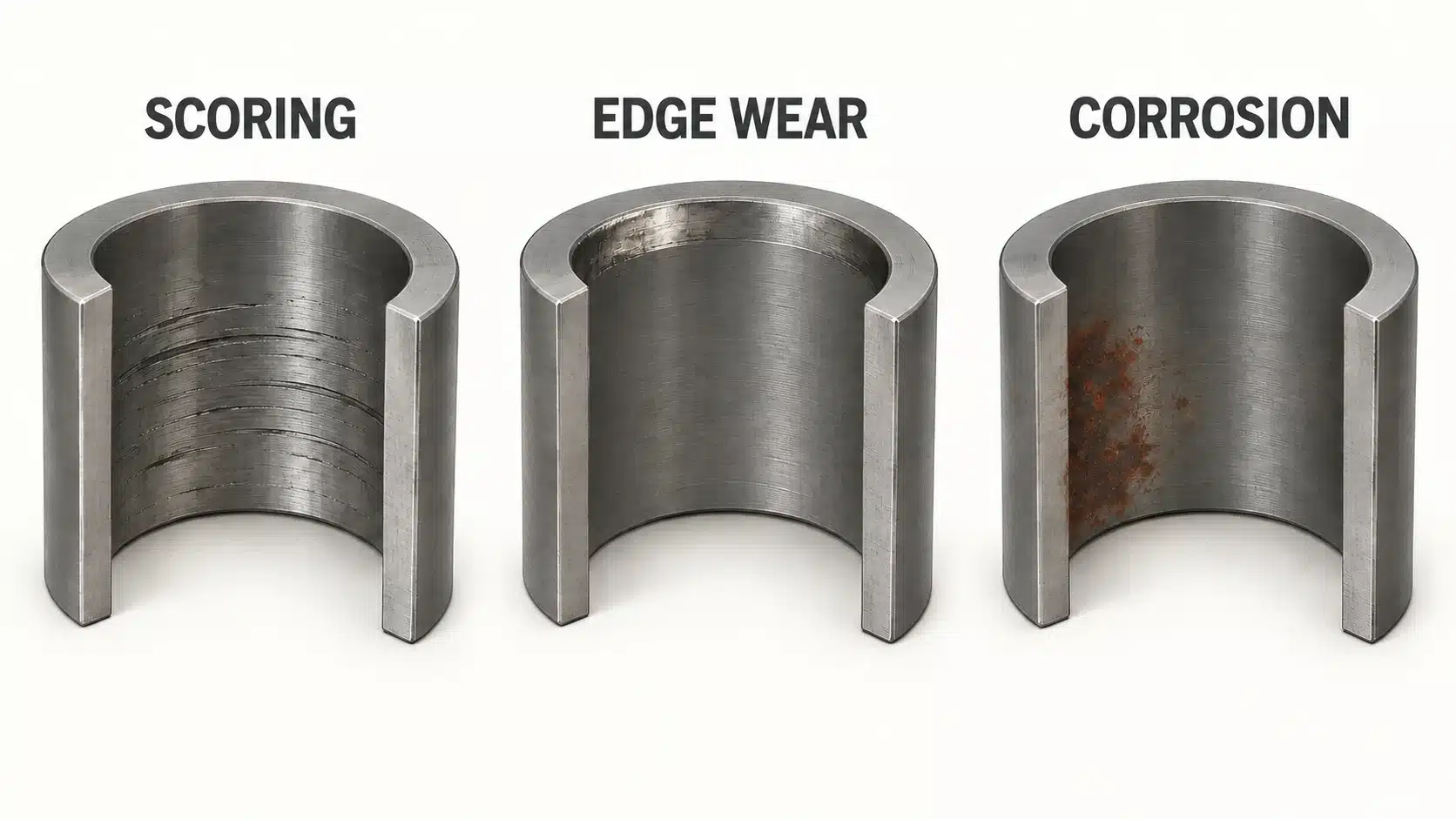
Surface appearance is useful when it is paired with measurements and service information. The following table proposes investigation routes. None of the observations proves a single cause.
| Observation | Follow-up investigation |
|---|---|
| Scratches or grooves with visible debris | Examine contamination entry paths, seal condition and the retained debris |
| Wear concentrated near one end | Check bore alignment, pin geometry, housing support and load direction |
| Local distress near an intended grease supply area | Verify passage alignment and actual lubricant delivery |
| Marks on the outside of a bushing that should remain fixed | Check retention, housing dimensions and evidence of movement in the bore |
| Corrosion on the pin or adjacent surfaces | Review water exposure, protection, storage and lubricant condition |
| Looseness returning soon after a repair | Compare the new inspection with the previous pin, bore and installed-clearance records |
GGB’s failure-analysis process includes examining abnormal wear, debris, deformation and damage outside the intended sliding surface, followed by a review of the operating conditions. The table above applies that investigative approach to practical questions about a linkage joint.
For example, suppose an inspection finds heavier wear at one end and a damaged seal at that same end. Contamination and misalignment are both reasonable subjects for investigation. Replacing only the seal may leave a geometry problem. Changing the bushing material may leave the contamination route. A repair becomes more defensible when the report explains which observations each proposed action addresses.
Build a useful specification before requesting a quote
A drawing establishes geometry. An application brief explains what the geometry must survive. Sending both makes it easier to compare suppliers on the same basis.
For a recurring linkage problem, prepare the following information:
- Joint identity and dimensions. Include machine configuration, pivot position, drawing revision, pin diameter, bushing length, wall thickness and housing arrangement.
- Loading and movement. State the load basis, known peaks, oscillation angle, cycle frequency and any significant dwell or impact events. Identify values that are estimates.
- Environment and lubrication. Describe dust, mud, water, temperature, seal arrangement, lubricant and the maintenance process that can actually be sustained.
- Mating components. Provide pin material, specified hardness and finish, housing material, fit requirements and relevant inspection results.
- Evidence and acceptance criteria. Include previous damage, hours or cycles to the reported problem, and the dimensional or functional limits that define an acceptable result.
Ask suppliers to state deviations explicitly. If one quote assumes a new pin and another assumes the existing pin will be reused, the prices do not describe the same repair. The same applies when a proposed material requires a seal change or a different lubrication arrangement.
For qualification, agree on a limited trial with inspection points and a defined endpoint. Record the assembly condition at installation, the work performed and the later measurements using a consistent method. A trial without a baseline can show that a part is still operating, but it provides much less evidence about its wear rate or the reason for improvement.
Also preserve batch identity and the specification revision. If the trial performs well, production supply should be tied to the same controlled requirements. A successful sample is useful only when the purchasing and inspection records make its construction repeatable.
Measure whether the repair has changed the outcome
A follow-up plan should be agreed before the machine returns to work. Decide what will be measured, who will record it and which finding will trigger further inspection. The following is a proposed way to structure that plan, rather than a manufacturer-prescribed service interval.
At installation, record the relevant dimensions and assembly clearance using the approved method. Keep the measurement locations clear enough that a different technician can repeat the check. Record the pin and bushing identities and note which seals, lubrication parts or housing features changed during the repair.
During the trial, log operating hours together with the work performed. Where practical, add a useful description of exposure, such as time spent on a particular attachment or in submerged work. If the application changes halfway through the trial, mark that point. Otherwise, a change in wear may be attributed to the replacement when the workload also changed.
At each agreed inspection, compare measurements taken under equivalent conditions. Record unusual noise, visible seal damage or lubricant-delivery problems as separate observations. A quieter joint is encouraging, but noise alone is not a dimensional measurement. Equally, a single clearance reading should be checked against the method and instrument before it is treated as a sudden change in wear.
Finally, interpret the result within the trial’s limits. If the pin, seals and bushing material all changed, improved performance supports the combined repair. It does not reveal how much improvement came from each change. If the trial ends while the joint remains acceptable, report the hours or cycles completed and the measured condition at that point. That is a useful result without turning an unfinished trial into a claim about ultimate service life.
This record makes the next purchasing decision easier. Suppliers can respond to a defined outcome, and the maintenance team can identify whether the original failure pattern has returned.
Make the next repair explain the previous failure
The strongest repair report connects each action to evidence. It might document a worn pin that was replaced, a housing restored to its approved dimensions, a damaged seal renewed and a lubricant-delivery problem corrected. Where material selection contributed to the failure, the report should explain the requirement that the replacement addresses.
This approach also improves cost comparisons. Ask what each option includes and what work it leaves for later. A low part price tells little about the cost of a joint if the scope excludes pin inspection, bore correction or follow-up measurement.
For a MYWAY application inquiry, include the drawing and operating information described above, together with photographs and inspection records from any previous failure. Product and contact information is available on the MYWAY website.
Frequently asked questions
Why do excavator linkage bushings wear out so quickly
Common causes include inadequate lubrication, abrasive contamination, misalignment and incorrect components. Investigate the complete pin-and-bushing assembly and its service history before deciding which cause applies. A replacement may wear again if the original operating or fit problem remains.
Can self lubricating bushings replace every greased excavator bushing
No. A replacement needs to satisfy the particular joint’s load, motion, dimensions, pin pairing and environmental requirements. Treat a change of bearing construction as an application review. Obtain the selected grade’s operating and maintenance instructions before changing the existing lubrication practice.
Do self lubricating bushings still need seals
They can. The ability to operate without routine grease does not establish suitability for an exposed, abrasive joint. SKF recommends external sealing for composite bearings under heavy contamination. The appropriate protection depends on the selected product and the joint design.
Is graphite bronze better than a PTFE composite bushing
There is no universal answer. Compare exact products against the same operating conditions. Ask about the base alloy or backing, sliding material, permissible duty, counterface requirements and test conditions. Broad commercial descriptions are insufficient for deciding whether a bearing will work in a particular pivot.
How often should excavator pins and bushings be greased
Use the interval and procedure in the applicable machine manual, including instructions for severe service. Identify the specific joint and machine configuration. Caterpillar directs owners to their Operation and Maintenance Manual for greasing locations and intervals.
Should the pin be replaced when the bushing is replaced
Inspect and measure it. Reuse depends on whether it meets the applicable requirements for dimensions, condition and surface properties. Include that decision in the repair record. A new bushing cannot correct an out-of-specification pin, so the two components should be evaluated together.
Does every worn linkage require line boring
No. The need for housing repair follows from measurements and the approved repair limits. A worn bushing alone does not establish that the housing requires line boring. Check bore size, shape and alignment before deciding how to restore the assembly.
How much play is acceptable in an excavator bucket linkage
Use the limits and measurement procedure for the relevant machine and joint. Movement observed at the bucket may include clearance from several connections. Record where and how the measurement was taken so that repeated inspections remain comparable. Avoid applying a generic clearance number to every excavator.
Can a pressure or pV rating predict bushing life
It provides part of a selection assessment. Load history, motion, temperature, mating surfaces and environmental conditions still need evaluation. GGB’s design guidance treats pressure and speed as application inputs rather than a universal service-life guarantee.
What should a supplier receive when a replacement fails early
Send the drawing revision, operating record, installation measurements and photographs taken before cleaning. Keep the matching pin, seals and debris where practical. State what failed, when it changed and how the problem was measured. That information supports a more useful response than the bushing alone.