
Recent Posts
Self-Lubricating Bushings in Hydraulic Cylinders: The Complete Engineering Reference for Design, Selection & Maintenance
Introduction
Self-lubricating bushings have become the default guiding solution in modern hydraulic cylinder design, replacing greased bronze and roller bearings in rod glands, piston guides, and pivot points. This article covers the working principles, material architectures (PTFE composite, graphite-plugged bronze, engineered polymer), performance data, selection methodology, installation best practices, and failure analysis for self-lubricating bushings in hydraulic cylinders. Drawing on published tribological research, OEM maintenance manuals, and field application data, it provides design engineers and maintenance teams with a practical decision-making framework for extending cylinder service life, reducing maintenance costs, and eliminating lubrication-related downtime. A dedicated FAQ section addresses the most common field questions, and a supplier introduction for MYWAY bushings is included at the end for procurement reference.
Table of Contents
1. Why Hydraulic Cylinders Are Moving Away from Greased Bearings
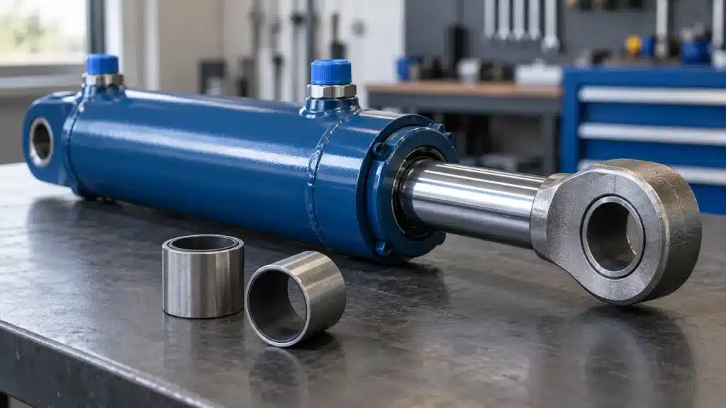
Hydraulic cylinders are the workhorses of construction, agriculture, mining, and industrial automation. Inside every cylinder, the piston rod and piston must be guided with enough precision to protect the seals, absorb side loads, and maintain concentric alignment. For decades, the standard approach was a bronze or bimetallic bushing that required regular greasing.
That model has a well-documented weakness. Grease lines break. Manual lubrication schedules get missed. In freezing conditions, grease channels clog. When a bronze bushing runs dry — even briefly — it seizes against the rod, scores the surface, and destroys the rod seal within hours. This is not a hypothetical risk. Field studies on navigation lock machinery found that broken grease lines caused cascading failures in bronze bushings, leading operators to seek self-lubricating replacements that could survive lubrication system neglect–.
Self-lubricating bushings solve this by building the lubricant into the bearing structure itself. Instead of relying on an external supply of grease or oil, these bushings contain solid lubricants — typically PTFE, graphite, or molybdenum disulfide — that transfer a microscopic film onto the mating shaft during operation. Once that transfer film forms, the bushing essentially lubricates itself. No grease fittings, no lubrication schedule, no downtime for regreasing.
The shift is not just about convenience. It is about reliability. A hydraulic cylinder that does not need external lubrication eliminates an entire class of failure modes: clogged grease lines, contaminated lubricant, missed service intervals, and environmental leakage from grease purge ports.
2. How Self-Lubricating Bushings Work Inside a Hydraulic Cylinder
2.1 The Transfer Film Mechanism
Understanding how these bushings work requires looking at what happens at the microscopic level during the first few operating cycles.
A self-lubricating bushing is not a solid block of lubricant. It is a composite structure: a structural backing material (steel, bronze, or polymer) combined with a sliding layer that contains the lubricant. When the shaft first moves against the bushing, the sliding layer sacrifices a micro-thin film of lubricant. This lubricant transfers to the shaft surface and bonds to it, forming what tribologists call a transfer film.
Once the transfer film is established, the sliding interface is no longer PTFE against steel — it is PTFE against PTFE. Friction drops. Wear becomes self-limiting because the transfer film replenishes itself as fresh lubricant is exposed from the bushing liner.
The quality of this transfer film depends heavily on the shaft surface finish. This is one of the most counterintuitive findings in self-lubricating bearing technology: a mirror-polished shaft is actually worse for bushing life than a slightly textured one. Empirical testing shows that a shaft surface roughness (Ra) between 0.2 μm and 0.4 μm is optimal. If the shaft is too smooth (Ra < 0.1 μm), the lubricant cannot anchor to the metal, leading to high friction and stick-slip behavior. If it is too rough (Ra > 0.8 μm), the shaft acts like a file and grinds away the bushing lining prematurely. One hydraulic cylinder manufacturer discovered this the hard way: after switching to super-polished stainless steel rods, their PTFE-lined bushings wore 40% faster. The fix was not a different bushing — it was de-polishing the rods back to a consistent 0.3 μm Ra.
2.2 Where Bushings Sit in a Hydraulic Cylinder
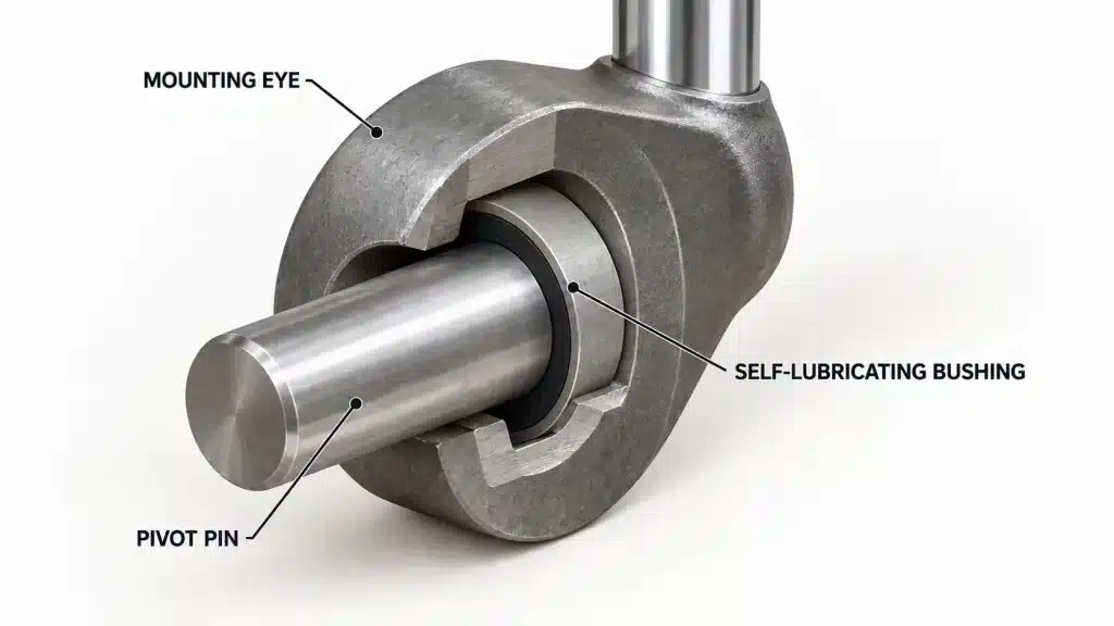
In a typical hydraulic cylinder, self-lubricating bushings serve three primary locations:
Rod guide bushing (gland bushing): Installed inside the cylinder head, this is the most critical bushing. It guides the piston rod, absorbs radial side loads, and provides a backing surface that prevents the rod seal from extruding under pressure. Without a properly functioning rod bushing, the rod seal fails almost immediately.
Piston guide ring: Mounted on the piston itself, these rings maintain concentric alignment between the piston and cylinder barrel. In long-stroke cylinders, piston guide rings are essential for preventing metal-to-metal contact and ensuring even seal loading.
Intermediate guide bands: Used in telescopic or extra-long cylinders to prevent rod deflection and buckling under compression loads.
Each location has different load profiles, motion patterns, and environmental exposure. A rod guide bushing experiences reciprocating motion with high side loads from the machine linkage. A piston guide ring experiences continuous sliding with primarily radial loads. These differences matter for material selection.
3. Material Types: PTFE Composite, Graphite Bronze, and Engineered Polymers
3.1 Steel-Backed PTFE Composite Bushings
This is the workhorse of modern hydraulic cylinder design. The structure is a three-layer sandwich:
Steel backing (0.7–1.5 mm): Provides structural rigidity and load-carrying capacity. The steel backing is what allows these bushings to handle dynamic pressures up to 140 N/mm² (approximately 20,000 psi).
Sintered bronze interlayer (~0.25 mm): A porous bronze layer sintered onto the steel backing. This layer serves two functions: it anchors the PTFE sliding layer mechanically, and it provides a thermal conduction path to carry heat away from the sliding surface–.
PTFE sliding layer (20–50 μm): A blend of PTFE with fillers such as bronze powder, carbon, glass fiber, or MoS₂. The fillers improve wear resistance and compressive strength beyond what virgin PTFE can achieve.
The performance envelope for steel-backed PTFE bushings is broad: operating temperatures from −200°C to +260°C, friction coefficients as low as 0.02–0.10, and the ability to run completely dry or with intermittent lubrication.
3.2 Graphite-Plugged Bronze Bushings
These bushings take a different approach. Instead of a thin surface layer, they use a solid bronze matrix with graphite plugs embedded in drilled holes or grooves around the bearing surface. As the shaft rotates or oscillates, graphite transfers to the mating surface and provides lubrication–.
Graphite-plugged bronze bushings excel in low-speed, high-load applications (static loads above 70 MPa) and high-temperature environments (up to 400°C). They are commonly found in mining equipment, marine applications, and heavy industrial machinery where loads are extreme and speeds are low.
The limitation is that graphite-plugged bushings need a “pumping” action — rotation or oscillation of sufficient amplitude — to release the graphite. In high-frequency, low-amplitude vibration (common in hydraulic cylinder rod guides), the graphite may not deploy correctly, leading to localized dry spots and premature wear.
3.3 Engineered Polymer Bushings (POM, Nylon, PEEK-Based)
Polymer bushings offer the lightest weight and the best chemical resistance. POM (acetal) and nylon bushings are cost-effective options for moderate loads and clean environments. PEEK-based bushings deliver higher temperature resistance and mechanical strength but at a significant cost premium.
For hydraulic cylinder applications, polymer bushings are typically used in piston guide rings rather than rod guide bushings, where the side loads are lower and the environment is protected by the cylinder barrel.
3.4 Material Comparison for Hydraulic Cylinder Applications
| Property | Steel-Backed PTFE | Graphite Bronze | POM/Nylon |
|---|---|---|---|
| Max dynamic load | 140 N/mm² | 70–100 N/mm² | 30–50 N/mm² |
| Max temperature | 260°C | 400°C | 80–120°C |
| Friction coefficient | 0.02–0.10 | 0.10–0.20 | 0.10–0.25 |
| Dry running | Excellent | Limited | Good |
| Contamination tolerance | Moderate | High | Low |
| Cost | Moderate | High | Low |
4. Why These Bushings Outperform Traditional Solutions
4.1 Maintenance Elimination Is Not a Luxury — It Is a Reliability Strategy
The most visible advantage of self-lubricating bushings is the elimination of lubrication maintenance. But the real benefit is not saving the labor cost of greasing. It is removing the failure modes that lubrication systems introduce.
Grease lines can be damaged by debris, pinched by machine movement, or blocked by hardened grease. When a grease line fails on a critical cylinder, the bushing may run dry for weeks before anyone notices. By the time the rod starts scoring, the damage is already done. Self-lubricating bushings have no such single point of failure.
4.2 Higher Load Capacity in a Smaller Package
Steel-backed PTFE bushings combine the dimensional rigidity of a metallic bearing with the friction properties of a polymer. This allows them to carry loads that would crush a solid polymer bushing, in a wall thickness (typically 1.0–2.5 mm total) that fits into the tight gland spaces of modern cylinder heads.
For context, a comparable bronze bushing with the same load capacity would need to be significantly thicker, requiring a larger cylinder head and a heavier overall assembly.
4.3 Stick-Slip Suppression
Stick-slip is the jerky, juddering motion that occurs when static friction is significantly higher than dynamic friction. In hydraulic cylinders, stick-slip causes position control problems, noise, and accelerated seal wear.
PTFE composite bushings have static and dynamic friction coefficients that are nearly identical (static ≤ 0.05, dynamic ≤ 0.10), which effectively eliminates stick-slip at normal operating speeds. Bronze bushings, by contrast, typically show friction coefficients of 0.18–0.24 under insufficient lubrication, creating the friction differential that drives stick-slip–.
4.4 Tolerance to Contamination and Boundary Conditions
Hydraulic cylinders in construction and agricultural applications operate in dirty environments. Dust, grit, and metal particles inevitably find their way past wiper seals.
PTFE composite bushings tolerate particulate contamination far better than rolling element bearings, which can be destroyed by a single hard particle in the raceway. The soft PTFE surface can embed small particles without catastrophic damage, and the transfer film re-establishes itself around minor surface disruptions
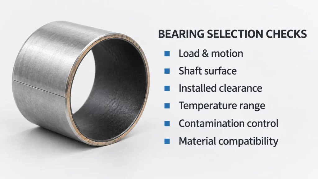
5. Selection Guide: Matching the Bushing to the Application
5.1 Step One: Calculate the Specific Load and PV
The starting point for any bushing selection is the specific load on the bearing surface:
P = F / (D × B)
Where F is the radial load in Newtons, D is the bushing inner diameter in mm, and B is the bushing length in mm. The result is in N/mm².
Once you have the specific load, calculate PV (pressure × velocity) to assess heat generation. PV is not a fixed material rating — it is a thermal limit. A bushing rated for PV = 5.0 at 25°C ambient may only handle PV = 2.5 at 100°C ambient because heat dissipation is less effective.
For hydraulic cylinder rod guide bushings, the velocity is the rod speed during extension and retraction. For piston guide rings, it is the same. For pivot bushings at the cylinder mounting points, the motion is oscillating and the velocity is typically low.
5.2 Step Two: Assess the Operating Environment
Temperature is the single most important environmental factor. PTFE composite bushings degrade above 260°C. Graphite bronze handles up to 400°C. If the cylinder operates near a heat source — engine exhaust, foundry equipment, or injection molding machinery — temperature becomes the primary constraint.
Chemical exposure matters for polymer and PTFE bushings. While PTFE is chemically inert to most hydraulic fluids, certain additives in fire-resistant hydraulic fluids (HFD, water-glycol) can attack the bronze interlayer. For these applications, specify a bushing with a compatible interlayer or a solid polymer construction.
5.3 Step Three: Match the Shaft Surface
As discussed earlier, the optimal shaft surface roughness for a PTFE composite bushing is Ra 0.2–0.4 μm. This is a “fine turned” or “ground” finish, not a polished finish. If the rod is already polished to Ra < 0.1 μm, consider light blasting or turning to restore the texture needed for transfer film adhesion.
Shaft hardness also matters. A hard shaft (HRC 50+) resists scoring and extends both shaft and bushing life. If the shaft is softer than the bushing’s embedded particles (such as bronze filler in the PTFE layer), the shaft will wear rather than the bushing — an expensive outcome.
5.4 Step Four: Consider the L/D Ratio and Wall Thickness
The length-to-diameter ratio (L/D) of the bushing affects guiding stability. For rod guide bushings, an L/D of 1.0–1.5 is typical. Shorter bushings are more prone to edge loading and can allow rod deflection that damages seals. Longer bushings increase the moment arm for side load resistance but add cost and require more cylinder head length.
Wall thickness for steel-backed PTFE bushings typically ranges from 1.0 to 2.5 mm total. The steel backing provides most of the structural rigidity, so the PTFE layer can be very thin without compromising load capacity.
5.5 Step Five: Verify the Fit and Clearance
Press-fit installation is standard for hydraulic cylinder bushings. The recommended housing tolerance is H7 with an interference fit of 0.01–0.03 mm. This interference ensures the bushing stays locked in the housing under vibration and thermal cycling.
However, press-fitting causes bore closure — the bushing’s inner diameter shrinks after installation. For a standard 50 mm PTFE-lined bushing, the ID typically shrinks by 0.02–0.05 mm. This must be accounted for during design, either by specifying a slightly oversized bushing or by planning for a post-installation sizing operation.
6. Installation, Maintenance, and Failure Analysis
6.1 Installation Best Practices
Pre-installation inspection: Before installing any bushing, inspect the piston rod or bore for scratches, burrs, dents, or displaced metal. A damaged shaft surface will destroy a new bushing and seal within hours.
Cleanliness: Clean the bushing bore and all seal grooves thoroughly. Even a small metal chip trapped between the bushing OD and the housing bore can create a stress riser that leads to cracking.
Lubrication during assembly: Apply a light coat of clean hydraulic fluid or compatible assembly grease to the bushing bore, the bushing OD, and all seal surfaces. This is not for ongoing lubrication — the bushing is self-lubricating — but to prevent scuffing during the initial press-fit.
Press-fit technique: Use a proper arbor press or hydraulic press with a driver that contacts the bushing evenly. Never hammer a bushing into place. For split or wrapped bushings, ensure the seam is positioned away from the primary load direction.
Edge chamfering: A 0.5–1.0 mm × 20° chamfer on the bushing edges prevents PTFE scuffing during installation and reduces edge stress concentrations.
6.2 Common Failure Modes and What They Mean
Excessive PTFE wear: Usually caused by abrasive contamination or overload. If the hydraulic fluid contains particles larger than 10 μm, they will act as grinding media against the PTFE surface. Solution: improve filtration to <10 μm and consider a filled PTFE material with higher wear resistance.
Delamination of the PTFE layer: The bronze interlayer can fail if the bushing experiences extreme thermal cycling or if the PTFE layer is damaged during installation. This is almost always an installation or application error, not a manufacturing defect.
Bore closure beyond specification: If the bushing ID shrinks more than expected after press-fit, the housing bore may be undersized or out-of-round. This creates excessive interference and can crack the steel backing.
Stick-slip despite self-lubrication: Usually indicates the shaft surface is too smooth (Ra < 0.1 μm) or the transfer film has been disrupted by contamination. Re-texture the shaft and re-evaluate filtration.
6.3 Maintenance Intervals
Self-lubricating bushings are not maintenance-free in the literal sense — they are maintenance-reducing. The bushing itself requires no lubrication, but the cylinder still needs periodic inspection of:
Rod surface condition (scratches, corrosion, wear)
Seal condition (leakage, hardening, extrusion)
Bushing clearance (rod play at the gland)
Hydraulic fluid cleanliness (filter condition, particle count)
In most hydraulic cylinder applications, a self-lubricating bushing will outlast the rod seal. When the seal is replaced, inspect the bushing for wear and replace if the clearance has exceeded the manufacturer’s specification. As a rule of thumb, rod bushing clearance should not exceed 0.15–0.20 mm for most industrial cylinders.
7. Real-World Applications and Performance Data
Self-lubricating bushings are used across a wide range of hydraulic cylinder applications:
Construction machinery: Excavator boom and arm cylinder pivots, bucket linkage bushings, and stabilizer leg guides. These applications combine high shock loads with dirty environments — exactly the conditions where self-lubricating bushings outperform greased bronze.
Agricultural equipment: Tractor loader cylinders, harvester header guides, and implement pivot points. The seasonal operating pattern (intense use followed by storage) makes lubrication maintenance unreliable, and self-lubricating bushings eliminate that risk.
Mining equipment: Continuous miners, roof bolters, and haul truck suspension cylinders. Graphite-plugged bronze bushings are often specified here because of the extreme loads and high temperatures.
Industrial automation: Injection molding machine cylinders, press cylinders, and material handling actuators. PTFE composite bushings provide the low friction and precise control needed for servo-hydraulic systems.
Marine and offshore: Deck cranes, hatch cover cylinders, and subsea actuators. Stainless steel-backed PTFE bushings resist corrosion while providing maintenance-free operation in inaccessible locations.
Field data from a U.S. Army Corps of Engineers study on navigation lock machinery found that self-lubricated bushings outperformed the oil-lubricated bronze bushings they replaced, with the added benefit of eliminating grease lines that were vulnerable to ice and debris damage
Frequently Asked Questions (FAQ)
Q1: Can self-lubricating bushings run completely dry in a hydraulic cylinder?
Yes. Steel-backed PTFE composite bushings are designed for dry running. The PTFE transfer film provides lubrication without any external fluid. However, in hydraulic cylinders, some oil mist or film from the rod seal inevitably reaches the bushing, which actually improves performance and extends life. The bushing does not require this oil, but it tolerates it well.
Q2: How do I know when to replace a hydraulic cylinder bushing?
Check the radial play between the rod and the bushing. If the rod can be moved more than 0.15–0.20 mm radially at the gland, the bushing is worn beyond specification. Other indicators include visible scoring on the rod surface, rod seal leakage that cannot be resolved by seal replacement alone, and abnormal noise during cylinder operation.
Q3: Can I replace a bronze bushing with a PTFE composite bushing without changing the housing?
In most cases, yes — if the housing bore dimensions are compatible with the PTFE bushing’s OD. PTFE composite bushings are typically thinner-walled than bronze bushings for the same load capacity, so you may need a spacer sleeve or a custom-sized bushing. Always check the press-fit interference specification for the specific bushing type.
Q4: What is the maximum side load a self-lubricating bushing can handle?
Steel-backed PTFE bushings can handle dynamic loads up to 140 N/mm² and static loads up to 250 N/mm². However, the limiting factor is usually not the bushing material but the housing and shaft. Excessive side loads can cause housing deformation or shaft deflection before the bushing itself fails.
Q5: Do self-lubricating bushings work with fire-resistant hydraulic fluids?
Most PTFE composite bushings are compatible with mineral oil, HLP, HFD, and water-glycol fluids. However, some fire-resistant fluids contain additives that can attack the bronze sinter layer. Always verify compatibility with the bushing manufacturer for the specific fluid formulation.
Q6: Why did my self-lubricating bushing fail after only a few hundred hours?
The most common causes are: (1) abrasive contamination in the hydraulic fluid, (2) shaft surface roughness outside the 0.2–0.4 μm range, (3) excessive press-fit interference causing bore closure, or (4) misalignment between the rod and bushing axis. In most “premature failure” cases, the root cause is an installation or system issue, not a bushing material defect.
Q7: How does temperature affect bushing performance?
Temperature affects both the load capacity and the friction coefficient. Above 100°C, the friction coefficient of PTFE composites can increase by up to 50% compared to room temperature. The load-carrying capacity drops by 30–50% at 100°C compared to 25°C. For high-temperature applications, graphite-plugged bronze bushings or PEEK-based composites are better choices.
100000+ Types of Bushings – Contact Us for Details