
Recent Posts
PTFE Composite Bushings and the Design Choices That Shape Bearing Life
Introduction
Think about the last bearing on a machine that anyone wants to grease. It may sit behind a guard, above a conveyor or inside a linkage that has to be dismantled before a grease gun can reach it. For that sort of position, a PTFE composite bushing is an attractive option. A suitable grade can run dry, and its thin wall leaves useful room for the shaft inside a small housing.
There is still some engineering to do. The sleeve does not arrive with its own finished counterface or a guarantee that the housing will stay round after assembly. Those details belong to the machine designer. They are also the details that can make two installations of the same bearing behave differently.
Suppose a new pivot feels fine when turned by hand, then gets stiff after the machine warms up. Ordering a more expensive bearing material may not address the cause. First check the fitted clearance, the temperatures of the surrounding parts and whether the housing is distorting. This article works through those decisions for metal-backed PTFE composite bushings, from the first load estimate to the questions worth answering before a production order.
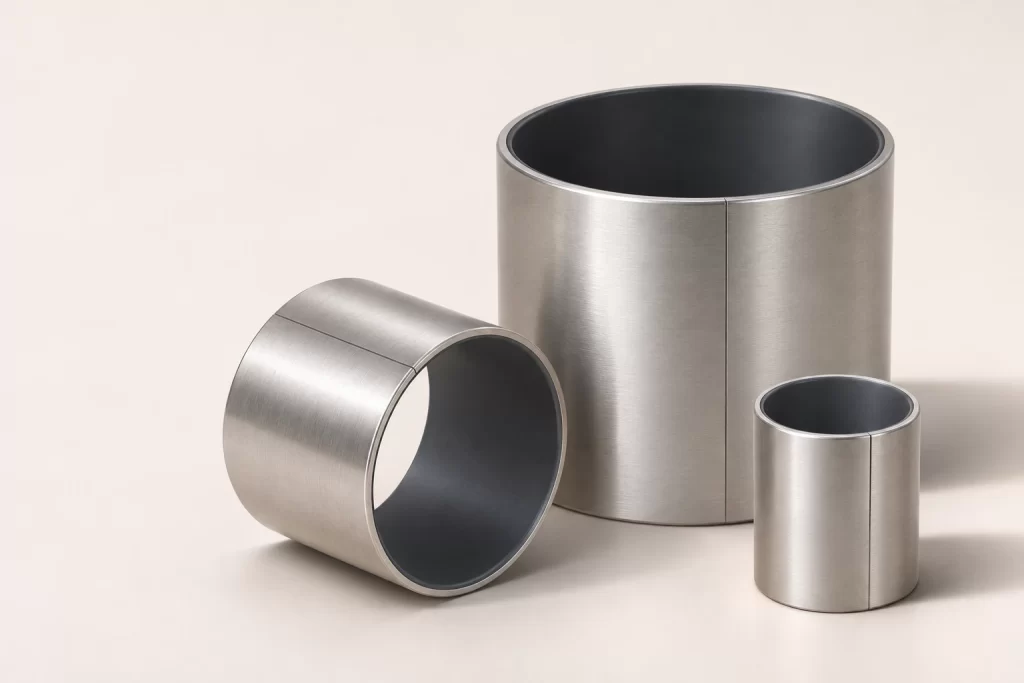
Table of Contents
1.What a PTFE composite bushing actually does
PTFE means polytetrafluoroethylene. In a metal-polymer plain bearing, a PTFE-based sliding material works with a supporting metal structure. A common construction has a steel backing, a porous sintered bronze intermediate layer and a thin PTFE compound at the running surface. The backing gives the sleeve its support; the intermediate layer anchors the sliding material. Formulations and layer arrangements vary, so the material designation matters.
This is different from a sleeve machined entirely from PTFE. It is also different from a bronze bushing with graphite plugs. Those products may all be described as self-lubricating bearings, but their fits, load behavior and finishing requirements are not interchangeable. For purchasing, specify the construction and grade alongside the dimensions. A photograph or the word composite leaves too much room for misunderstanding.
During dry running, suitable PTFE bearing systems can develop a transfer film on the mating shaft. The contact then changes as the bearing runs in. That is one reason the shaft surface is part of the bearing specification rather than a separate detail left to machining. A new shaft material, coating or finish can change performance even when the bushing stays exactly the same.
The MYWAY self-lubricating bushing range is a useful starting point for comparing available constructions. Treat the product family as the beginning of selection. The final choice should refer to a particular material, its intended lubrication condition and the drawing requirements for the complete assembly.
2. Where these bearings earn their place
Take a packaging-machine linkage as an example. The shaft swings backwards and forwards instead of making full revolutions. There is little room around the pivot, and grease near the product would create an extra cleaning job. A dry-running PTFE sleeve belongs on the shortlist for that arrangement. Its suitability still depends on how heavily the joint is loaded and what reaches the bearing from the surrounding process.
The practical attraction is easy to see: a compact sliding contact, no rolling elements to accommodate, and potentially no routine grease supply. Valve mechanisms, actuator linkages and equipment guides can present similar reasons to consider a composite plain bearing. These are possible applications, rather than a claim that one grade will serve every valve or actuator.
What about a joint that hardly moves? Low speed sounds easy until you consider the contact. A heavily loaded pivot making a very small movement works much the same patch of lining repeatedly. Frequent reversals also give a lubricated contact little opportunity to develop a separating oil film. A suitable PTFE compound can help with that duty, but a slow shaft is not automatically a lightly stressed bearing.
An outdoor pivot raises another question: how will dirt be kept out? A lining that needs no grease can still be worn by grit. Likewise, a guide running in oil needs a material and clearance suitable for that oil, even if a dry-running version of the sleeve looks identical. Describe the surroundings before choosing the grade.
If the design calls for continuous fast rotation, substantial shaft bending or severe shocks, leave room to compare other bearing arrangements. Sometimes the better answer is a lubricated metallic bushing or a rolling bearing. It is much easier to make that choice while the housing is still a drawing than after tooling has been ordered.
3. Start with the movement and load history
Before opening a bearing catalogue, describe one cycle of the mechanism in ordinary language. The shaft moves, stops, reverses and waits. How far does it move? How quickly? What is pulling or pushing on it during each stage? That description exposes details which can disappear inside a single entry marked operating speed.
For example, a linear guide might travel quickly for one second and then sit still for nine. Averaging the travel over ten seconds gives a much lower speed, but the bearing still has to cope with the faster moving interval. Give the stroke, actual moving speed and pause separately. Include startup after a long shutdown if starting force is important to the actuator.
An oscillating shaft needs an equally clear description. A twenty-degree movement could mean twenty degrees in total, or twenty degrees on each side of center. Write down the total sweep and cycles per minute. If the motion changes near the ends of travel, include that information too. It avoids having two people perform apparently reasonable calculations for different movements.
Then work through the forces. Separate the normal working load from the load during a jam, rapid stop or impact. Two sleeves supporting one shaft do not necessarily share the load equally. Their spacing and the location of the applied force determine the support reactions; shaft stiffness influences the contact. A simple sketch with the forces and dimensions marked can clarify more than a long description.
There is no need to disguise uncertainty with extra decimal places. If the force is an estimate, say so and give a realistic range. For a new machine, that tells MYWAY what still needs checking. For an existing machine, measured running conditions and a photograph of the arrangement can help explain why the original bearing is wearing unevenly.
4.Use bearing pressure and PV as screening checks
For a simple cylindrical radial bushing, nominal bearing pressure is commonly estimated by dividing radial load by projected bearing area. That area is the shaft diameter multiplied by the effective bearing length. It is not the full curved surface area inside the sleeve. Keep the units consistent: newtons divided by square millimeters gives pressure in N/mm², which is numerically equal to MPa.
Consider an illustrative joint carrying 1,200 N on a 20 mm shaft with an effective bearing length of 25 mm. The projected area is 500 mm², so nominal pressure is 2.4 MPa. If the sliding speed is 0.08 m/s, the resulting PV value is 0.192 MPa·m/s. These are example calculations, not a rating or an approval for a MYWAY product.
PV combines pressure and sliding velocity into a useful first check on the duty. It does not describe every source of wear or overheating. A design can have an acceptable nominal PV and still suffer from abrasive contamination, poor heat removal or concentrated edge loading. The temperature and operating conditions associated with a published limit must therefore stay attached to that limit when making a comparison.
Avoid combining the highest load and highest speed from separate catalogue entries as though both are available together. They may refer to different conditions. Likewise, a short intermittent movement should be described with its actual motion and rest periods rather than reduced to a low average speed that conceals a demanding moving interval. Ask for the applicable operating envelope and a basis for the required service life.
5.Give the shaft surface as much attention as the bushing
A bearing supplier can supply a consistent lining and still have little control over the surface it runs against. This is where otherwise sensible designs often leave a gap. The shaft drawing should identify its material, hardness where required, surface treatment and roughness. The bearing contact length also needs to be free of burrs, corrosion and raised damage from handling.
Specify the finish recommended for the selected PTFE compound. There is no single roughness number that should be copied across every metal-polymer bearing. An abrasive surface can remove lining material rapidly, while a mirror-like appearance does not by itself prove that the contact will behave as intended. Texture direction, waviness and isolated defects can matter even when a measured average roughness falls within the drawing limit.
Shaft hardness is another application decision. A hardened or coated counterface may help resist damage and wear, but the coating must be suitable for the contact. Check its final finish, adhesion and condition after processing. If the shaft is plated or coated after machining, specify the finished diameter. Otherwise, an apparently small coating allowance can consume part of the running clearance.
For prototypes, keep the actual production process in mind. A hand-polished sample can give a flattering result if production shafts will come straight from a different finishing process. Use a representative shaft for the useful test. Keep its inspection record, too. If the next batch wears differently, you will want to know whether the counterface changed before blaming the sleeve.
6.Design the fit around the installed bearing
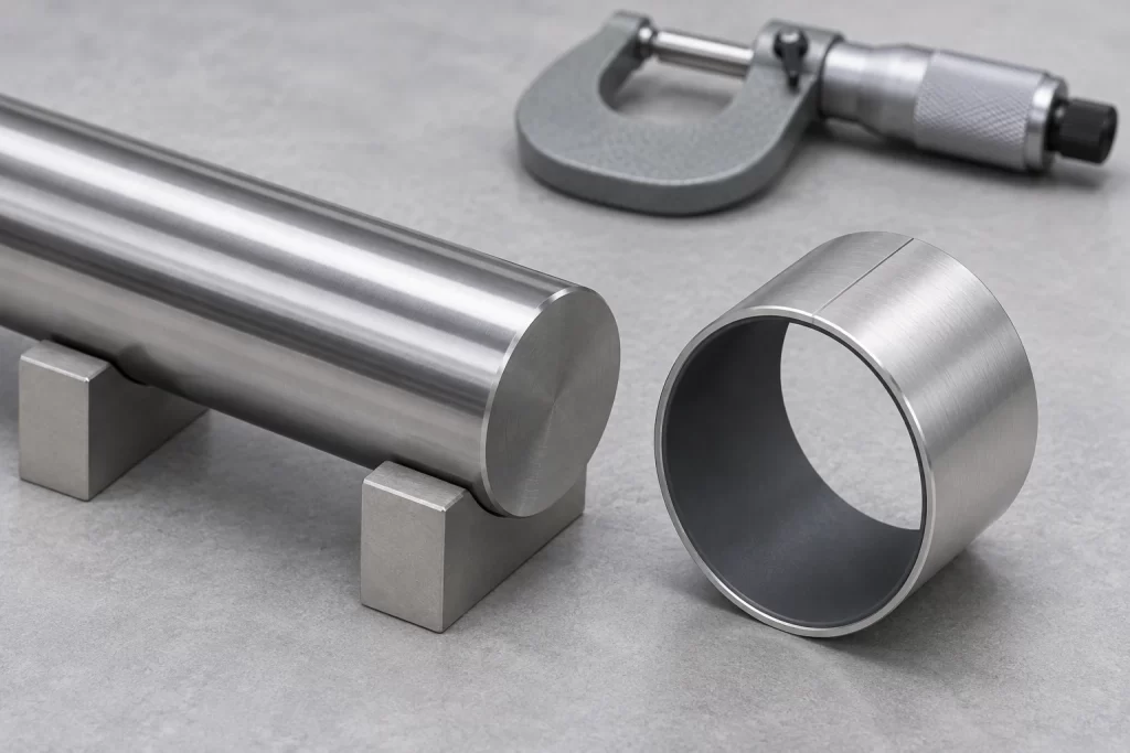
A thin wrapped sleeve relies on its housing for support. Pressing it into the bore changes its shape and influences its internal diameter. Measuring a loose bushing with ordinary calipers therefore cannot tell the whole story about operating clearance. Establish the housing and shaft tolerances using the selected bearing data, then agree how the installed dimensions will be checked.
The housing needs adequate stiffness as well as the right nominal bore. A thin wall can deflect; a split housing can distort when its fasteners are tightened. In either case, the bearing may become tight in one direction while still looking acceptable in another. Check bore geometry under the conditions in which the machine will actually run, including assembly torque where relevant.
Too little clearance can increase friction and produce binding. Excessive clearance can allow movement that the mechanism cannot tolerate and may change how the load is distributed. A shaft that can just be pushed through is not proof of a good fit. Work through the tolerance limits for both mating parts and the change caused by pressing in the sleeve. The clearance has to make sense during operation, including at the expected temperature.
Pay special attention when replacing an existing bushing. Matching inside diameter, outside diameter and length does not establish equivalence. Wall thickness tolerances and lining construction may differ. If an old sleeve was machined after fitting, copying that assembly procedure into a thin PTFE-lined replacement could remove the working surface that made the new bearing attractive in the first place.
7. Check temperature through the whole assembly
The surrounding air temperature is only part of the thermal picture. Sliding generates heat at the contact, and the shaft and housing carry some of it away. A bearing next to a motor, heater or hot process fluid can start from an elevated temperature before friction contributes anything. Describe those heat sources when requesting a material recommendation.
Different materials expand at different rates. An aluminum housing, a steel shaft and a steel-backed sleeve do not necessarily keep the same dimensional relationship as temperature changes. The housing can also influence how firmly the sleeve remains retained. A cold fit check is useful, but it is not a substitute for evaluating the working temperature range of the assembled joint.
A published maximum temperature is not a promise of unchanged load capacity or wear life at that temperature. The suitable duty can depend on load, speed, exposure time and the selected lining. For a prototype, record starting torque, running force and clearance at relevant temperatures. Let the assembly approach its normal thermal condition rather than judging the design from the first few revolutions.
8. Choose the form that matches the load direction
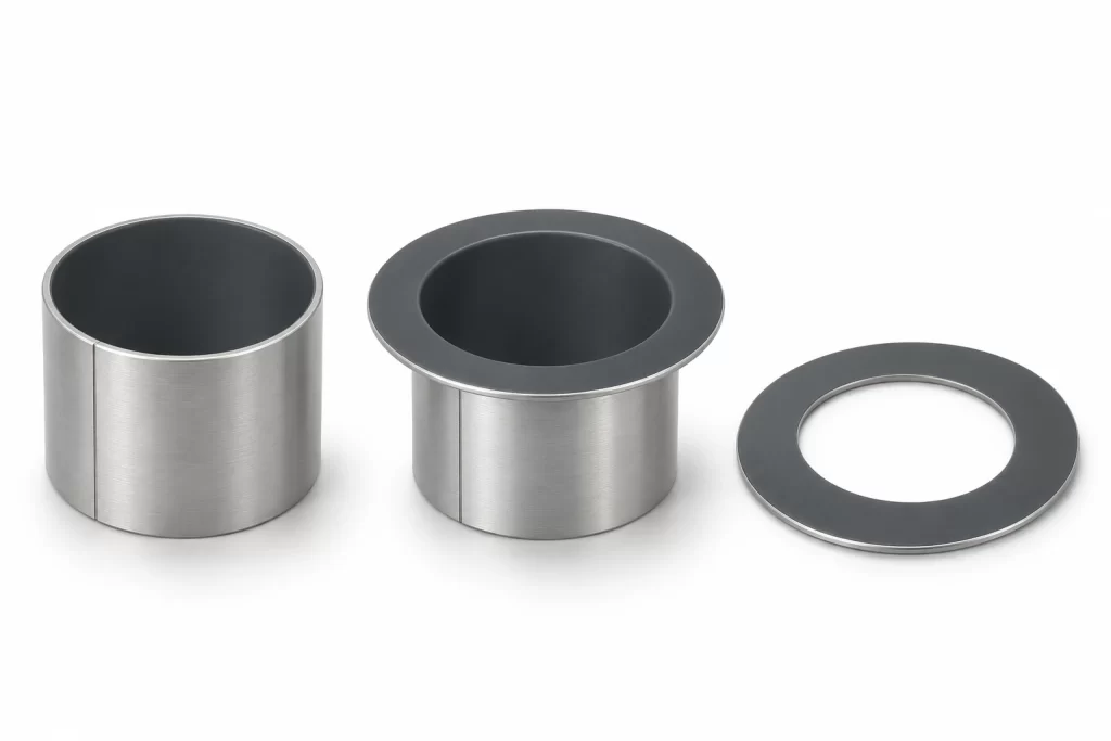
A straight sleeve mainly supports radial load. If a shaft shoulder also pushes along the axis, the design needs a suitable thrust surface. A flanged PTFE bushing can combine radial guidance with an axial sliding face in a compact part, but the flange load must still be assessed. The presence of a flange does not create an unlimited thrust bearing.
A separate thrust washer can be useful when axial load needs its own bearing area or when assembly favors separate components. Its sliding face must contact the moving part, with the backing supported appropriately. Make the intended orientation clear on the assembly drawing. For a flange, check the shaft shoulder geometry so that a fillet does not interfere with the bearing corner.
Bearing form | Primary duty | Drawing detail to confirm |
Straight sleeve | Radial guidance | Installed bore and effective length |
Flanged sleeve | Radial and axial contact | Flange face and shoulder clearance |
Thrust washer | Axial sliding contact | Face orientation and retention |
Sliding strip or plate | Guided sliding | Support and attachment method |
Increasing sleeve length may reduce nominal pressure, but it also makes alignment more important. A long bearing around a deflecting shaft can concentrate contact near an edge. Before choosing a longer part, consider whether the support spacing, shaft stiffness or housing alignment needs attention. More nominal area is helpful only when the assembly can use it.
9.Decide the lubrication and environmental conditions early
Dry running is a useful capability, not a complete description of an application. Some PTFE composite grades also work with external lubrication, but the choice of fluid and the method of supply need review. Do not assume that adding grease will automatically improve a bearing selected for dry operation. Specify whether lubrication is continuous, occasional, present only during assembly or absent throughout service.
Dust, chips and grit can enter a sliding contact and change its behavior quickly. A protected indoor pivot and an exposed agricultural linkage are different design problems even at the same calculated pressure and speed. Consider seals, shields and a practical path for cleaning before deciding that a maintenance-free lining removes the need for environmental protection.
For wet or corrosive service, assess the complete bearing. The chemical resistance associated with PTFE does not establish the resistance of the backing, intermediate material, coating or exposed edges. Give MYWAY the actual fluid, concentration and temperature rather than describing the environment simply as chemical resistant. Also identify cleaning agents, because washdown exposure can differ from normal operation.
Color is not a material certificate. Dark, red or pale linings can represent different formulations, and outside metallic colors may come from surface coatings. MYWAY lists steel-backed PTFE bushings with a specified construction. For an order, confirm the exact grade and any required material declarations instead of approving a substitute by appearance alone.
10.Make installation part of the design
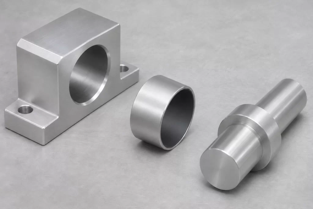
Installation begins with the housing entrance. A suitable lead-in and a clean, deburred bore help the sleeve enter squarely. Use a correctly sized mounting tool that supports the bushing during pressing. An improvised tool bearing on a small area can deform the edge. A shaft with an unprotected sharp step can also damage the lining as it passes through the installed sleeve.
Where a wrapped bushing has a butt joint, follow the specified orientation relative to the principal load. Make that instruction visible to the assembler when orientation matters. Do not rely on a person at the press to infer it from a general arrangement drawing. The installation instructions should also state which surfaces may receive any assembly lubricant and which must remain clean.
Do not ream, hone or scrape a thin PTFE running layer as a routine way to correct a tight assembly. Some materials allow controlled sizing or other finishing, but that permission must come from the chosen grade and process specification. If a fitted sleeve is tight, investigate the housing, shaft and installation method before removing material from the bearing.
11.Test the joint against a useful acceptance plan
Before testing, define what success means for the machine. It might include a maximum starting force, acceptable radial play after a target number of cycles or a temperature limit near the bearing. Agree those limits before the test starts. Otherwise, one person may judge the sample by how quietly it runs while another rejects the same part for play in the linkage.
Use the intended shaft finish, housing fit and assembly method. Apply representative motion and loading, including reversals and pauses. Where contamination or temperature matters, include it deliberately in the validation plan. A short clean bench test can establish basic function, but it does not establish a service interval for a dusty or thermally demanding installation.
When a test shows wear, inspect the pattern before changing the material. Damage concentrated at one end suggests a different investigation from scratches around the whole bore. Check alignment, debris, shaft condition and the fitted dimensions. For example, photograph the contact after the initial run and again at the agreed inspection points, with the cycle count attached. Keep the shaft measurements with those images. A note saying worn after testing gives the next person almost nothing to investigate.
12.Frequently asked questions
Can PTFE composite bushings run without grease
Many are designed for dry sliding, provided the selected grade is suitable for the load, movement, shaft and environment. Confirm that condition when ordering. Dry-running capability does not remove the need to check wear, keep abrasive debris out or assess whether the machine still needs periodic inspection.
Are PTFE composite bushings the same as solid PTFE sleeves
No. A metal-backed composite uses a supporting metal structure with a PTFE-based sliding layer. A solid PTFE sleeve has a different construction and different dimensional behavior. Treat a change between them as a bearing redesign, including fit, support, thermal behavior and the method used to establish clearance.
What shaft roughness should be specified
Use the recommendation for the exact bearing compound and operating condition. Include a measurable finish requirement on the shaft drawing rather than asking only for a smooth surface. If a coating is applied, the finish and diameter requirements should refer to the completed counterface after that process.
Can the bore be machined after installation
Do not assume so. Thin running layers can be damaged or removed by ordinary bore finishing. Ask whether the selected material permits sizing, what process is allowed and how much material may be affected. Resolve clearance through the approved fit and assembly specification wherever the bearing design requires it.
Will a longer bushing always last longer
No. Extra length increases projected area, but its benefit depends on alignment and the way the shaft carries load. A deflecting shaft may load the ends unevenly. Review shaft stiffness and support geometry alongside nominal pressure before using a longer sleeve as the answer to a wear problem.
Is a flanged bushing enough for axial load
It may be, if the flange material, contact area and duty are appropriate. Check axial load separately from the radial sleeve calculation. The mating shoulder must contact the intended sliding face without interfering at the corner. A separate thrust washer may be easier to size or assemble in some arrangements.
What information is needed for a quotation
Send the drawing, quantity, shaft and housing details, load, motion, temperature and lubrication condition. Add the target life or acceptance criteria if available. For an existing wear problem, include clear photographs and measured fitted dimensions. Those details help distinguish a material question from a fit or alignment problem.
13.Discuss your PTFE bushing application with MYWAY
An effective inquiry gives MYWAY enough context to discuss a bearing that fits the machine, not just the purchase description. Include the inside diameter, outside diameter, length and any flange dimensions, together with tolerances and the intended installation method. State whether the drawing describes a new design, a replacement part or an existing bearing that needs better performance.
If the duty is not fully defined, share what is known and identify the open questions. A preliminary drawing with a realistic motion description is more useful than choosing a material from a photograph. For a production project, include the sample requirement, expected order quantities and the checks needed before release.
Contact MYWAY about your PTFE composite bushing requirements with your drawing and operating details. Use the discussion to confirm the construction, fit recommendations and validation steps before committing the design. That preparation helps turn a compact sleeve into a bearing arrangement that is practical to manufacture, assemble and maintain.
100000+ Types of Bushings – Contact Us for Details