
Recent Posts
Copper Alloy Bushings for Rolling Mills: Comprehensive Material Selection and Application Adaptation to Ensure Efficient Mill Operation
Introduction
In steel rolling production lines, copper alloy bushings serve as critical foundational components that carry rolling forces and ensure equipment precision, with their performance directly determining mill availability and product quality. Whether in hot or cold rolling processes, rolling mill bushings must withstand enormous radial and axial loads, impact loads during bite-in, and thermal cycling stresses from alternating high temperatures and cooling water. Taking the short-stress-path rolling mill as an example, the stress state of bushings in the roll gap adjustment mechanism directly affects the spatial position stability of the rolling line—bushing wear or fixing bolt fracture leads to pull rod sagging and rolling line deviation, subsequently causing surface defects such as head warping, scratching, and folding, and in severe cases, even resulting in major equipment failures such as rolling mill bearing burnout and abnormal roll wear. Therefore, material grade selection, structural parameter design, lubrication method matching, and manufacturing process control of bushings all directly relate to mill operational reliability and product dimensional accuracy.
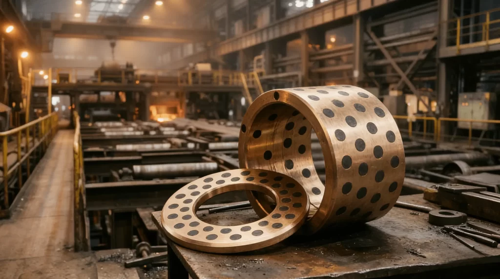
Table of Contents
1. Core Functional Positioning and Stress Characteristics Analysis of Copper Alloy Bushings in Rolling Mills
Copper alloy bushings in rolling mills are primarily installed between pull rods and supports, within roll gap adjustment mechanisms, and at roll bearing housings, serving multiple critical functions: first, providing precise radial support and axial positioning to keep rolls or pull rods moving within prescribed spatial trajectories, ensuring parallelism of upper and lower roll axes and uniformity of the roll gap; second, directly withstanding and transmitting the enormous reaction forces generated during rolling, including vertical rolling force components and horizontal lateral displacement forces; third, ensuring smooth operation of the roll gap adjustment mechanism under loaded conditions, where bushings and mating shafts must maintain sufficient clearance to compensate for thermal expansion without causing adjustment failure due to excessive wear; fourth, absorbing and buffering impact kinetic energy during bite-in, reducing damage risks from sudden loads to mill housings and bearings. Taking the short-stress-path rolling mill as an example, the pull rod is constrained within the support through upper and lower bushings, with the entire mill’s dead weight and the reaction forces measuring several meganewtons transmitted through these bushings to the support. The impact force peak during bite-in can reach two to three times the steady-state rolling force, superimposed with shear stress from lateral workpiece oscillation, subjecting bushings to complex combined stress states involving compression, shear, and bending. The wear resistance and dimensional stability of bushings directly determine the retention period of roll gap adjustment accuracy. Field experience indicates that when inner diameter wear exceeds 2% of the original wall thickness (typically corresponding to an absolute wear amount of approximately 1.5 to 2.0 millimeters), roll gap adjustment exhibits noticeable lag and nonlinear response, signaling the need for replacement. Therefore, bushing design must fully consider boundary conditions including peak loads, lubrication conditions, temperature fluctuation ranges, and expected maintenance cycles to reasonably determine material grades and wall thickness parameters.
2. Systematic Overview of Service Condition Extremes and Failure Modes of Rolling Mill Bushings
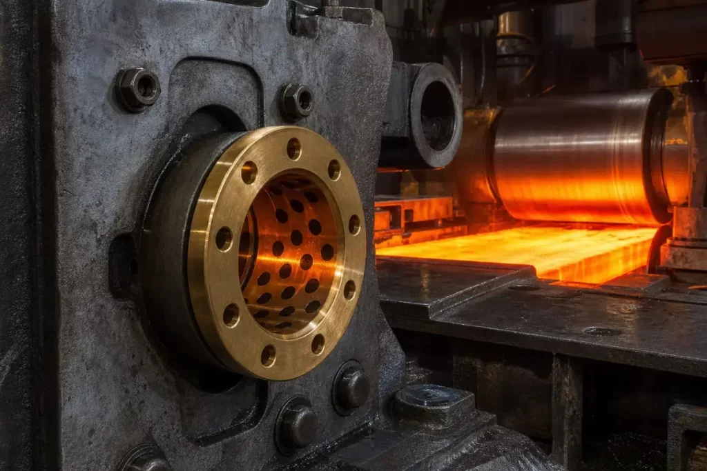
The service conditions endured by rolling mill bushings are extremely severe, primarily manifested in the following aspects: contact stresses caused by rolling forces typically reach 30 to 60 MPa, with some roughing mill stands even exceeding 80 MPa during bite-in peaks; workpiece temperatures in hot rolling processes can reach 950 to 1150 degrees Celsius, and although bushings do not directly contact the red-hot steel, heat conducted through rolls and bearing housings raises bushing operating temperatures to 150 to 250 degrees Celsius, with intermittent cooling water spraying creating thermal cycling stresses that readily induce thermal fatigue cracking; regarding lubrication conditions, although forced lubrication or oil mist lubrication is specified in design, actual lubrication often falls into boundary lubrication or even mixed lubrication regimes due to cooling water washout and oxide scale ingress; additionally, roll changing operations, workpiece bite-in impacts, and vibrations during rolling all impose additional dynamic loads on bushings. Under the combined effect of these conditions, rolling mill bushing failure modes exhibit diverse characteristics, primarily including: eccentric wear causing the inner bore to become bell-mouthed or elliptical, resulting in uneven clearance between the pull rod and bushing, leading to off-center loading on roll gap adjustment screws and adjustment obstruction; fatigue fracture of fixing bolts under alternating shear stress, causing the bushing to detach from its mounting seat and the pull rod to oscillate violently after losing radial constraint, severely threatening mill safety; thermal stress-induced axial cracking or radial through-cracks that render the bushing incapable of load bearing; adhesive and abrasive wear due to poor lubrication, manifested as scoring, scratches, and material spalling on the inner surface; and synergistic effects of electrochemical corrosion and wear, particularly in cooling water with hardness or weak acidity, where dealuminification corrosion of copper alloys significantly accelerates material loss. Deep failure analysis reveals that most cases can be traced to unreasonable force structure design—where the resultant force vector borne by the bushing is incompatible with the arrangement of fixing bolts, exceeding their shear capacity—or overly conservative wall thickness design where thick-walled structures, despite higher stiffness, hinder stress distribution and heat transfer, instead concentrating thermal stress on the surface. Some older mill bushings employ integral thick-walled pure copper cast structures with wall thicknesses typically reaching 25 millimeters or more, while the actual effective wear layer is concentrated only within the surface 2 to 3 millimeter range, meaning substantial quantities of copper alloy material merely serve as structural filler, resulting in severe material waste and cost burden. Consequently, improvement directions should focus on two aspects: first, decomposing combined forces through structural optimization to reduce the load burden on individual bushing sets; second, adopting composite materials or composite structural processes to reduce consumption of scarce copper alloys while maintaining surface wear resistance.
3. Commonly Used Cast Copper Alloy Material Grade Systems and Selection Criteria
Rolling mill bushing material selection primarily follows cast copper alloy grade systems specified in national standards, with tin bronze and aluminum bronze series being the most widely applied in practice. Within the tin bronze category, ZCuPb10Sn10 (grade 10-10 leaded bronze) is most representative, featuring uniformly distributed free lead particles in the copper matrix. Lead possesses self-lubricating properties, forming a solid lubricating film during sliding friction that significantly reduces the friction coefficient and adhesion tendency. Simultaneously, tin solution-strengthens the matrix, enhancing alloy hardness and wear resistance, making it suitable for plain bearing applications with lateral pressure or boundary lubrication conditions. This material boasts a peak load capacity of 60 MPa with excellent conformability and anti-seizure properties, making it highly suitable for matching with steel pull rods or roll necks, particularly well-adapted to bimetallic centrifugal casting processes and serving as the preferred working surface material for steel-backed copper composite bushings. Another grade, ZCuSn10P1 (10-1 tin-phosphor bronze), exhibits higher strength, greater elastic modulus, and superior fatigue resistance compared to leaded bronze, making it suitable for wear-resistant components under high-cycle loading. The aluminum bronze series is represented by ZCuAl10Fe3 (10-3 aluminum bronze) and ZCuAl10Fe5Ni5 (10-5-5 aluminum bronze), where 10-3 aluminum bronze demonstrates excellent comprehensive mechanical properties with tensile strength exceeding 500 MPa and yield strength above 200 MPa, combined with good casting fluidity and resistance to seawater and weak acid corrosion, widely applied in rolling mill adjusting nuts, slide plates, worm gears, and other high-strength wear-resistant structural components. Nickel-containing 10-5-5 aluminum bronze maintains relatively high strength and hardness at elevated temperatures, suitable for hot rolling locations where operating temperatures exceed 200 degrees Celsius. Beyond these standard grades, some high-load mills also employ beryllium bronze (such as QBe2) for special-purpose bushings. Beryllium bronze after solution and aging treatment can achieve HRC 36 to 42 hardness with non-magnetic properties and excellent thermal conductivity, but at higher cost, generally reserved for critical positioning bushings in precision mills. In actual selection work, comprehensive trade-offs must consider factors including load magnitude (both peak and average rolling forces), lubrication conditions (adequate oil lubrication, oil mist lubrication, boundary lubrication, or even dry friction), operating temperature range (whether exceeding 150 degrees Celsius), mating shaft material and surface hardness, and expected maintenance and replacement cycles. For roll gap adjustment bushings requiring both heavy load capacity and long-term dimensional stability, tin bronze grades such as C90700 or CuSn10 have gained widespread adoption due to their excellent impact toughness, low friction coefficient, and stable dimensional change rate, becoming standard configuration materials for most mill manufacturers.
4. Steel-Backed Copper Composite Bushings—A Proven Cost-Effective Alternative Solution Explained
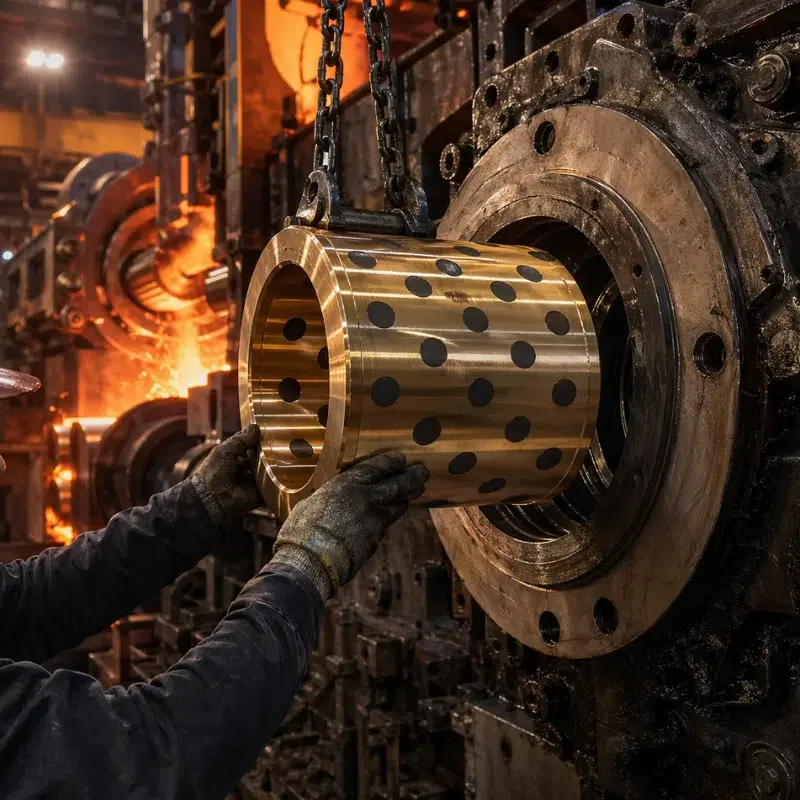
Steel-backed copper composite bushings represent a composite structural alternative developed to address the low material utilization and high manufacturing costs of traditional thick-walled pure copper bushings. This solution employs Q345 low-alloy high-strength structural steel or high-quality carbon structural steel as the substrate (steel backing), with ZCuPb10Sn10 or ZCuSn10P1 copper alloy melt poured onto the preheated steel inner wall through centrifugal casting, achieving atomic-level metallurgical bonding between the copper alloy and steel backing to form a robust composite interface. The copper alloy layer is applied only to surfaces requiring wear-resistant mating, typically controlled to a thickness of 5 to 8 millimeters, significantly less than the 25 millimeter-plus integral wall thickness of traditional pure copper bushings. This steel-copper composite structure combines the advantages of both materials: the steel backing provides superior tensile strength, impact toughness, and structural rigidity to effectively resist elastic deformation and impact loads from rolling forces; the inner copper alloy layer ensures excellent sliding friction characteristics, thermal conductivity, and anti-adhesive wear resistance. Regarding material consumption, compared to equivalent-sized integral pure copper bushings, steel-backed copper composite bushings reduce copper alloy consumption by approximately 36%, while overall material costs decrease by about 20 to 30% due to the significantly higher price of copper alloys versus steel. Beyond cost advantages, steel-backed copper composite bushings also offer superior mechanical properties—the elastic modulus of steel is approximately three times that of copper alloys, meaning composite bushings of equivalent cross-section exhibit higher overall rigidity, beneficial for maintaining rolling line spatial position accuracy. In terms of manufacturing processes, key steps for steel-backed copper composite bushings include: machining specific dovetail or spiral grooves on the steel inner wall with thorough degreasing cleaning; preheating the steel body in resistance furnaces to specific temperature ranges of 350 to 450 degrees Celsius before pouring, where temperature control precision directly affects bonding strength between copper alloy and steel backing; maintaining casting environment relative humidity below 60% to avoid hydrogen-induced porosity defects. Post-casting components undergo stress-relief annealing, followed by precision machining where final product coaxiality, roundness, and cylindricity errors are controlled within 0.01 millimeters, with surface roughness reaching below Ra 1.6 micrometers. This composite bushing technology has completed installation validation on rolling mill adjusting nuts, slide plates, flanged sleeves, guide sleeves, and other components across multiple steel enterprises, with no adverse reactions observed during no-load pressure tests and hot commissioning. One detail users should note is that exposed steel backing surfaces lack the corrosion resistance of copper alloys and may develop localized rust under prolonged humid conditions or cooling water spray environments, but with grease coverage or where minor rusting is acceptable, such appearance changes do not affect service performance or lifespan.
5. Design Improvement Examples and Force Optimization Approaches for Bushings in Roll Gap Adjustment Structures
Taking a certain type of short-stress-path bar mill as an example, its roll gap adjustment mechanism frequently experienced fixing bolt fracture issues in the bushings. On-site disassembly inspection and force analysis revealed that in the original design, axial rolling forces and radial off-center loads borne by the pull rod were concentrated entirely on the upper and lower bushings, with the bushings secured within the support by several M16 socket head cap screws. The shear stress on these bolts approached the material’s yield limit, and combined with the fatigue accumulation effect of bite-in impacts, bolts fractured after thousands of operating hours. The improvement concept centered on adding a positioning step on the pull rod body while installing a retaining ring at the corresponding position in the support bore, plus an auxiliary wear sleeve between the step and retaining ring. This redistributed loads originally borne independently by two bushings as follows: the upper bushing primarily carries radial loads, the lower bushing provides auxiliary radial positioning and partial axial loads, and the newly added auxiliary wear sleeve absorbs impact loads and partial off-center moments. After this structural modification, loads on each load-bearing component were reduced to varying degrees, with peak contact stress on the bushings decreasing by approximately 30%, and the safety factor of fixing bolts increasing from the original 1.2 to above 2.5. More importantly, the pull rod’s guidance within the support became significantly smoother, with contact marks on the bushing inner walls transforming from localized eccentric wear zones to uniformly distributed friction bands, effectively eliminating eccentric wear and localized overload. After implementation, roll gap adjustment accuracy retention time extended from the original 72 hours to over 200 hours, bushing replacement cycles extended from monthly to quarterly, and fixing bolt fracture failures were completely eliminated. This example demonstrates that bushing performance depends not only on material itself but equally on the rationality of associated structural design—through measures such as force distribution, load path optimization, and additional auxiliary supports, mill reliability can be significantly improved without altering bushing materials or dimensions. For new mill lines or production lines undergoing upgrades, it is recommended to introduce finite element analysis tools for coupled stress field and temperature field simulations of bushings and their mounting structures during the design phase, identifying stress weak points and thermal stress concentration areas to optimize wall thickness distribution, chamfer dimensions, and bolt layouts.
6. Self-Lubricating and Boundary Lubrication Technologies for Copper Alloy Bushings and Their Applicable Scenarios
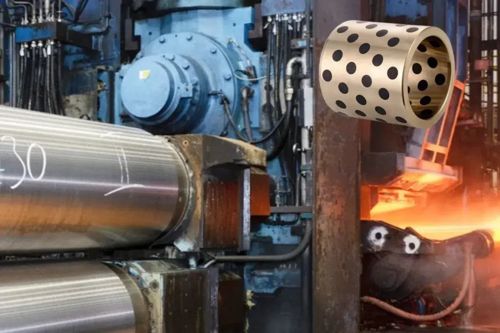
At certain specific locations in rolling mills—such as sliding seats of guide devices, swing shaft sleeves of loopers, and some adjustment mechanisms with difficult access for forced lubrication—grease supply pathways are challenging to arrange or maintenance access is limited. Traditional copper bushings in such scenarios often accelerate wear due to insufficient oil supply. For these issues, oil-impregnated sintered bronze bushings and PTFE-coated boundary lubrication bushings offer effective low-maintenance or even maintenance-free solutions. Oil-impregnated sintered bronze bushings use tin bronze powder as raw material, pressed and high-temperature sintered into porous matrixes with interconnected porosity, where pore volume typically accounts for 15 to 30% of total volume, subsequently impregnated with lubricating oil (such as high-viscosity mineral oil or synthetic ester oil) under vacuum or heating conditions. During operation, frictional heat between the shaft and bushing causes the oil in pores to expand by heat and exude to friction surfaces forming an oil film; when operation ceases and temperature drops, oil is reabsorbed into pores through capillary action, achieving self-adaptive oil supply-return cycles. These bushings generally allow sliding speeds of 0.1 to 1.0 meters per second, with load capacity affected by porosity, and static load safe values around 20 to 35 MPa, suitable for low-speed, moderate-load, intermittent-duty locations. Another category of boundary lubrication bushings, represented by DX or SF-2 type copper-steel composite structures, feature a three-layer construction: a low-carbon steel or carbon structural steel strip substrate, an intermediate sintered spherical bronze powder layer approximately 0.2 to 0.3 millimeters thick on the steel substrate, and a surface layer of PTFE (polytetrafluoroethylene) and modified POM (polyoxymethylene) composite filled in bronze powder pores, with surface layer thickness about 0.01 to 0.03 millimeters and regularly distributed oil reservoirs or pockets. This composite structure achieves friction coefficients in the range of 0.05 to 0.25, operating temperature range of -40°C to +130°C, maximum allowable sliding speed of 2.5 meters per second, and ultimate load capacity (static) of 140 N/mm². Even without external oil supply, stable low-friction operation is maintained through solid lubricants and minor oil reserves in the surface layer. After application of these copper-steel composite boundary lubrication bushings in rolling mill auxiliary equipment, lubrication frequency reduced from once per shift to monthly or even quarterly regreasing, representing over 90% reduction, while replacement time was significantly shortened, making them highly suitable for modern continuous rolling production lines with requirements for low maintenance and high availability.
7. Breakthrough Applications and Process Matching Challenges of Copper Roll Sleeve Technology in Twin-Roll Casting Production
Another major breakthrough for copper alloys in rolling mill core components is the industrial application of copper roll sleeves in twin-roll casters, which has fundamentally transformed the efficiency and product range of traditional casting-rolling production. Traditional steel roll sleeves are typically made from forged steel or alloy cast steel with thermal conductivity of only 25 to 35 W/(m·K). This relatively low thermal conductivity limits solidification heat transfer rates during casting-rolling, keeping casting speeds in the range of 800 to 1000 mm/min for extended periods. Steel roll sleeves can effectively produce only 1xxx series (pure aluminum), 8xxx series (aluminum-lithium alloys), and limited 3xxx series (Al-Mn alloys) aluminum alloy products. For 5xxx (Al-Mg) and 6xxx (Al-Mg-Si) series high-strength aluminum alloys with wide solidification ranges and high hot cracking tendencies, producing qualified cast-rolled strips with steel roll sleeves was nearly impossible. Copper roll sleeves achieve thermal conductivity of 200 to 300 W/(m·K), approximately eight to ten times that of steel roll sleeves. This exceptional heat transfer performance enables rapid solidification of molten metal within the roll gap, with significant grain refinement and effective suppression of macro-segregation. After introducing advanced German copper roll sleeve technology, a domestic steel enterprise (JISCO) overcame three core challenges—thermal assembly clearance control, precision turning and grinding, and process parameter matching—through five years of technical research, ultimately achieving stable industrial operation of copper roll sleeves. Actual production data shows that with copper roll sleeves, 1xxx series plain sheet casting speeds increased from the original 800 mm/min to 2250 mm/min, representing an 86% productivity improvement. More importantly, copper roll sleeves elevated the qualification rate of cast-rolled feedstocks for medium-to-high strength aluminum alloys such as 5052, 3004, and 6016 from near zero to over 98%, successfully achieving large-scale production of 5xxx and 6xxx series aluminum alloys via casting-rolling, replacing the previously mandatory hot rolling-cold rolling long process route, significantly reducing production costs and energy consumption. The successful application of copper roll sleeves under high-speed, high-heat-flux conditions fully demonstrates the irreplaceable role of copper alloy materials in extreme heat transfer and mechanical composite scenarios, while pointing the direction for subsequent development of larger-specification, higher-strength copper roll sleeves. Current research and development of new copper roll sleeves is progressing in areas including copper alloy formulation optimization (adding trace chromium, zirconium, rare earth elements), roll sleeve surface strengthening treatments (laser cladding, nitriding), and online temperature control system improvements, aiming to further enhance copper roll sleeve service life and product surface quality.
8. Full-Process Key Control Points and Quality Assurance Measures in Copper Bushing Manufacturing
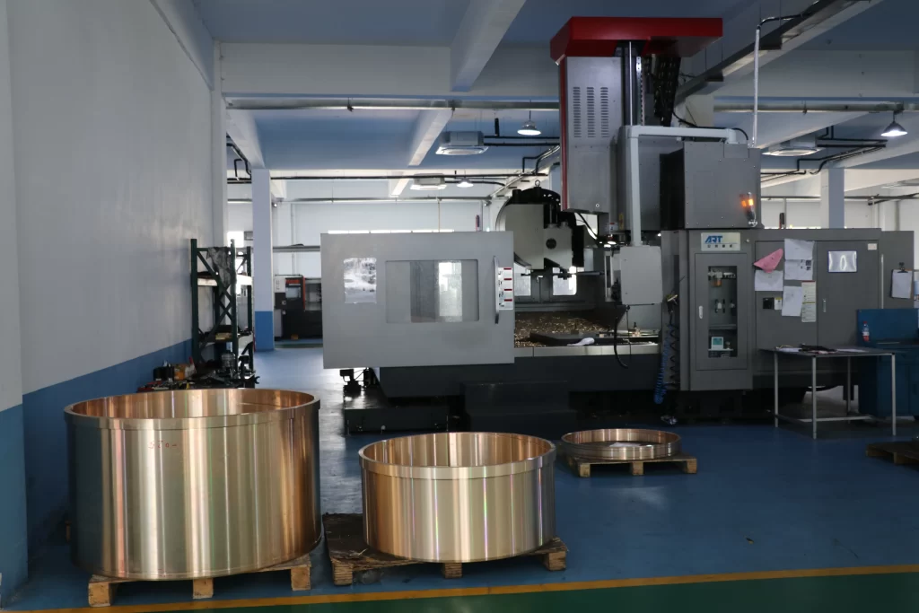
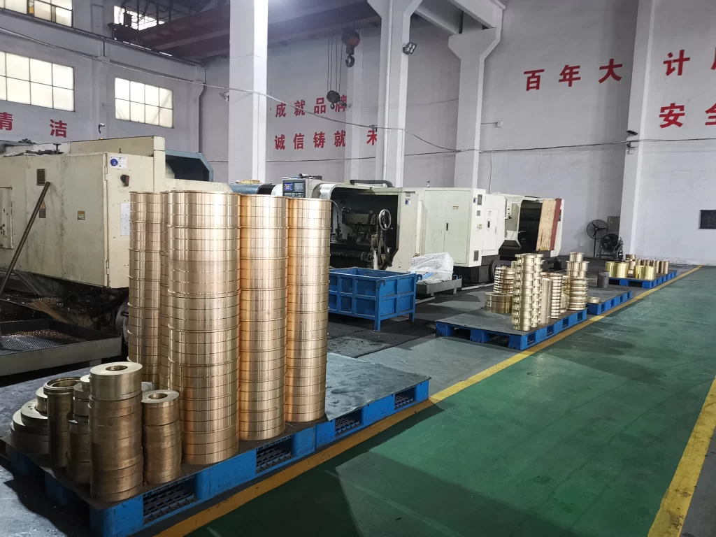
The manufacturing quality of copper bushings directly determines their in-service performance and service life, requiring establishment of strict quality control systems at every stage from melting to final precision machining. In centrifugal casting operations, to address the tendency of tin bronze and leaded bronze alloys toward inverse segregation, precise control of pouring temperature and mold rotational speed is essential: excessively high pouring temperatures aggravate reverse migration of lead or tin elements, causing inconsistent chemical composition between inner and outer walls; insufficient mold speed results in poor filling and loose structure, while excessive speed causes severe specific gravity segregation. For mass production of rolling mill bushings, centrifugal casting offers the highest efficiency and most dense internal structure, but requires real-time temperature monitoring and automatic speed regulation systems to ensure quality consistency for each product. In steel-backed copper composite processes, inner wall pretreatment of the steel body represents one of the most critical steps—machining specific spiral or dovetail grooves to increase mechanical interlocking, followed by ultrasonic cleaning or high-temperature degreasing to thoroughly remove surface oils, oxide scales, and particulate contaminants. Preheating temperature of the steel body before pouring is the core control parameter for metallurgical bonding quality: insufficient preheating causes molten copper to solidify prematurely upon contact with the steel wall, creating cold shuts or weak bonding; excessive preheating increases oxidation of the steel inner wall, forming brittle oxide films that weaken bond strength. Typically, preheating temperature is set 50 to 100 degrees Celsius below the phase transformation point of the steel material, with specific values requiring experimental optimization based on steel grade, wall thickness, and copper alloy pouring temperature. Additionally, workshop environmental temperature and humidity significantly affect porosity defects—when relative humidity exceeds 65%, hydrogen dissolved in the copper melt increases markedly, and hydrogen gas released during solidification without sufficient time to escape forms pinhole porosity, severely reducing material density and mechanical properties. The precision machining stage employs CNC lathes and grinders with separate rough and finish machining processes, with intermediate stress-relief aging treatment after rough machining to release residual cutting stresses. During finish machining, spindle speed, feed rate, and depth of cut are strictly controlled to ensure final product outer diameter tolerance, inner diameter tolerance, coaxiality, roundness, and cylindricity all achieve IT6 to IT7 grade precision levels specified in design drawings, with surface roughness controlled within Ra 1.6 micrometers. Pre-delivery final inspection items include dimensional inspection (go/no-go gauge and coordinate measurement), visual inspection (casting defects and machining flaws), hardness sampling (Brinell hardness test), and batch-based tensile property and crushing tests. Only bushings passing all inspection items may be delivered for user installation.
9. Factors Affecting Copper Bushing Service Life and Extension Strategies
The actual service life of rolling mill bushings varies considerably, ranging from weeks to over a year, primarily attributable to differences in usage conditions, maintenance levels, and spare part quality. The primary factor affecting bushing life is clearance control—insufficient installation clearance causes the bushing to seize the shaft journal under thermal conditions, resulting in severe wear or even burnout; excessive clearance exacerbates dynamic impact and fretting wear, shortening fatigue life. Typically, the recommended assembly clearance between rolling mill bushings and mating shafts is 0.1 to 0.15% of shaft diameter, with correction based on thermal expansion from operating temperature increases. The second critical factor is lubrication conditions, including whether the selected lubricant grade matches operating conditions, whether oil supply volume and pressure remain stable, and whether lubricating oil is contaminated by cooling water and oxide scale. Field practice demonstrates that regular testing of copper and iron content in lubricating oil provides indirect indication of bushing and mating shaft wear rates, serving as an effective predictive maintenance tool. The third factor is operational standardization during roll changes and maintenance procedures—improper disassembly methods (such as hammering bushing end faces without using dedicated pullers) can cause hidden initial damage to bushings, progressively developing into cracks or material spalling during subsequent service. The fourth factor is stability of rolling process parameters—frequent schedule changes, bite speed fluctuations, tension control failures, and other abnormal conditions subject bushings to unpredictable additional loads, accelerating fatigue damage accumulation. To extend bushing service life, the following strategies are recommended: establish reasonable roll change schedules and online inspection frequencies, with visual inspection and temperature measurement of roll gap adjustment sensitivity and bushing working areas per shift; implement precision filtration systems with oil contamination monitoring to ensure lubricant cleanliness not lower than NAS Class 8; perform dimensional spot checks on bushings during scheduled maintenance and establish individual bushing wear records, using historical data trends to predict optimal replacement timing, avoiding both premature replacement causing spare waste and delayed replacement risking equipment failure.
10. Comprehensive Evaluation Model for Bushing Selection and Future Technology Development Trends
Rolling mill bushing selection is a systematic decision-making process involving multidimensional factors. A scientific selection methodology should include the following five evaluation dimensions: First, equipment type and position characteristics—short-stress-path mills, high-rigidity mills, prestressed mills, caster-rollers, and other machine types have significantly different load characteristics and installation space requirements for bushings. Second, load spectrum analysis—accurately obtain parameters including peak rolling force, average rolling force, impact frequency, vibration amplitude, etc., to calculate minimum required wall thickness and load safety factor. Third, thermal condition assessment—determine temperature variation curves at bushing installation locations during steady-state operation and cooling stoppages, selecting appropriate copper alloy grades and clearance compensation values accordingly. Fourth, lubrication and maintenance conditions—clarify whether forced circulating lubrication systems, oil mist lubrication devices, or only manual periodic grease application are available on-site; for locations with limited lubrication conditions, oil-impregnated sintered or boundary lubrication type bushings are prioritized. Fifth, total life cycle economic evaluation—comprehensively compare initial procurement costs, installation labor costs, expected service life, maintenance frequency, and production losses from bushing failures across different selection options, using bushing cost per unit production as the final decision metric. Looking ahead, rolling mill bushing development trends will primarily focus on the following areas: material innovation direction—incorporating solid lubricant particles such as graphite, molybdenum disulfide, hexagonal boron nitride into copper alloy matrixes to develop gradient-structured self-lubricating copper-based composites for extreme dry friction and high-temperature conditions; process advancement direction—powder metallurgy, semi-solid forming, and additive manufacturing technologies will gradually be applied to bushing production, enabling complex internal oil circuit structures and gradient porosity designs, further enhancing product performance uniformity and controllability; intelligent monitoring direction—embedding miniature temperature sensors and wear monitoring sensors within bushings, combined with wireless transmission technology for online real-time monitoring of bushing service status, providing data support for genuine predictive maintenance; green manufacturing direction—through composite structural design and copper alloy scrap recycling technologies, reducing rare metal consumption intensity and decreasing energy consumption and emissions during casting processes. It is foreseeable that next-generation rolling mill bushings will no longer be single pure copper castings, but rather systematic technical solutions integrating advanced materials, intelligent sensing, and green manufacturing concepts, providing more reliable support for metallurgical rolling equipment toward high-speed, precision, and long-life development.
FAQ
Q1: What are the commonly used copper alloy grades for rolling mill bushings and their applicable conditions?A:Commonly used grades include ZCuPb10Sn10 (10-10 leaded bronze), featuring excellent self-lubricating properties from lead content, suitable for plain bearings with lateral pressure and boundary lubrication conditions, peak load capacity of 60 MPa, and the preferred working surface material for steel-backed copper composite bushings; ZCuAl10Fe3 (10-3 aluminum bronze), offering high strength, corrosion resistance, and good casting fluidity, suitable for rolling mill adjusting nuts, slide plates, worm gears, and other high-strength wear-resistant structural components; ZCuSn10P1 (10-1 tin-phosphor bronze), with superior fatigue resistance for precision positioning bushings under high-cycle loading; and beryllium bronze QBe2, providing extremely high hardness after aging treatment for critical positioning bushings in special precision mills, though at higher cost.
Q2: What are the advantages and limitations of steel-backed copper composite bushings compared to pure copper bushings?
A:Advantages: using Q345 steel as substrate with inner copper alloy layer reduces overall material costs by 20-30% and copper consumption by approximately 36%; the steel backing’s high rigidity and strength enhance overall anti-deformation capability and impact toughness; metallurgical bonding through centrifugal casting ensures composite interface reliability. Limitations: exposed steel backing surfaces are less corrosion-resistant than full-copper structures and may rust in humid or cooling water spray environments, though this does not affect performance under grease-covered conditions; manufacturing process control requirements are stricter, with high sensitivity to casting temperature and steel preheating temperature, making quality control somewhat more challenging.
Q3: What are the common failure modes of bushings in roll gap adjustment mechanisms and their root causes?
A:Common failure modes include four types: eccentric wear causing the inner bore to become bell-mouthed or elliptical, resulting in roll gap adjustment obstruction; fatigue fracture of fixing bolts under alternating shear stress, causing bushing detachment; axial or radial cracking from thermal cycling stress; and adhesive and abrasive wear due to poor lubrication. Root causes primarily include unreasonable force structure design where the resultant force borne by the bushing exceeds bolt shear capacity; excessive wall thickness causing thermal stress concentration; and cooling water ingress causing lubrication failure combined with electrochemical corrosion.
Q4: How can one determine when rolling mill bushings need replacement? What are the recommended replacement criteria?
A:Replacement should be scheduled when inner diameter wear exceeds 2% of original wall thickness, typically corresponding to 1.5 to 2.0 millimeters absolute wear, where roll gap adjustment exhibits noticeable lag and nonlinear response. Additionally, signs such as roll gap adjustment obstruction, rolling line deviation causing warped or scratched products, frequent fixing bolt fractures, or abnormal bearing temperature rise warrant immediate inspection. It is recommended to establish individual bushing wear records and predict optimal replacement timing through periodic measurement trend analysis.
Q5: What production bottlenecks has copper roll sleeve technology solved in casting-rolling, and what are current application results?
A:Traditional steel roll sleeves with thermal conductivity of only 25 to 35 W/(m·K) limited casting speeds to 800 to 1000 mm/min and could only produce 1xxx, 3xxx, and 8xxx series low-alloy products. Copper roll sleeves achieve thermal conductivity of 200 to 300 W/(m·K), eight to ten times that of steel, increasing casting speeds to 2250 mm/min with an 86% productivity improvement, while elevating qualification rates for 5052, 3004, 6016, and other medium-to-high strength aluminum alloys from near zero to over 98%, successfully enabling large-scale casting-rolling production of 5xxx and 6xxx series aluminum alloys.
Q6: How should the assembly clearance for rolling mill bushings be determined, and what are the consequences of excessive or insufficient clearance?
A:Recommended assembly clearance is generally 0.1 to 0.15% of shaft diameter, corrected for thermal expansion from operating temperature increases. Insufficient clearance causes the bushing to seize the shaft journal under thermal conditions, resulting in severe wear or shaft burnout; excessive clearance exacerbates dynamic impact and fretting wear, shortening fatigue life and reducing roll gap adjustment precision and stability.
Q7: What scenarios are oil-impregnated sintered bronze bushings and PTFE boundary lubrication bushings respectively suitable for?
A:Oil-impregnated sintered bronze bushings suit low-speed (0.1 to 1.0 m/s), moderate-load (20 to 35 MPa), intermittent-duty locations such as guide sliding seats and tilting shaft sleeves, using pore-stored oil for adaptive lubrication. PTFE boundary lubrication bushings (DX/SF-2 type) suit moderate-speed (up to 2.5 m/s), medium-to-high load (static load up to 140 N/mm²) locations with limited lubrication access, achieving friction coefficients of 0.05 to 0.25 and reducing lubrication frequency by over 90%.
Q8: How should one choose between tin bronze and aluminum bronze for rolling mill applications?
A:Tin bronze (such as ZCuPb10Sn10, CuSn10) offers excellent self-lubrication, conformability, and anti-seizure properties with low friction coefficient, suitable for sliding friction pairs under boundary or oil mist lubrication, such as roll gap adjustment bushings and roll neck bearing bushings. Aluminum bronze (such as ZCuAl10Fe3) provides high strength, corrosion resistance, and impact resistance, suitable for heavily loaded and impact-bearing threaded pairs, slide plates, worm gears, and other structural components, though with slightly higher friction coefficient requiring adequate lubrication.
Q9: What are the key control points in manufacturing steel-backed copper composite bushings?
A:Key control points include: dovetail or spiral groove machining and thorough degreasing cleaning of the steel inner wall; preheating temperature control (typically 350 to 450 degrees Celsius) before pouring—excessive temperature thickens oxide layers weakening bond strength, while insufficient temperature causes cold shuts and weak bonding; casting environment relative humidity controlled below 60% to avoid porosity defects; post-casting stress-relief annealing; and precision machining stage dimensional accuracy and coaxiality control.
Q10: What are the lubrication requirements for rolling mill bushings, and how should lubricants be selected?
A:Rolling mill bushings should be equipped with forced circulating or oil mist lubrication systems with oil supply sufficient to maintain a complete oil film between bushing and shaft, and oil cleanliness not lower than NAS Class 8. Lubricants typically selected are extreme-pressure gear oils or rolling mill specialty lubricating oils, with viscosity grade determined by operating temperature—higher viscosity grades (ISO VG 460 to 680) for high-temperature locations, moderate viscosity (ISO VG 220 to 320) for ambient temperature locations, with good demulsibility and rust protection required.
Q11: What heat treatment processes are applied to copper bushings, and what are their effects on performance?
A:Tin bronze and leaded bronze typically undergo stress-relief annealing at 250 to 350 degrees Celsius for 2 to 4 hours to eliminate residual stresses from casting and machining, stabilizing dimensions and structure to prevent stress deformation during service. Aluminum bronze can undergo solution and aging treatment: solution at 850 to 900 degrees Celsius, aging at 300 to 400 degrees Celsius, significantly increasing hardness and strength but reducing plasticity and toughness—adoption depends on specific service conditions.
Q12: Why do rolling mill bushings develop eccentric wear, and how can it be prevented?
A:Eccentric wear fundamentally results from asymmetric forces, potentially from: non-concentric installation of pull rod and support, horizontal rolling line offset, lateral forces from bite-in impacts, or uneven pre-tightening of bushing fixing bolts. Prevention measures include: ensuring installation coaxiality controlled within 0.02 millimeters; optimizing structural design to distribute lateral forces; using high-precision torque wrenches for bolt tightening according to specifications; regularly inspecting and recording wear pattern distribution, promptly investigating and correcting installation or force issues when biased wear trends are detected.
Q13: What impact does cooling water have on rolling mill bushing service life?
A:Improper cooling water management severely shortens bushing life through three mechanisms: cooling water washout dilutes or flushes away oil films, causing boundary or dry friction accelerating wear; dissolved corrosive substances (chlorides, sulfates) induce electrochemical corrosion creating synergistic interaction with wear; cooling water ingress into bushing-shaft clearances causes localized chilling, increasing thermal stress and inducing micro-cracks. Countermeasures include optimizing cooling water nozzle direction and flow, adding seals to prevent water ingress, and selecting aluminum bronze with better corrosion resistance or adding corrosion inhibitors.
Q14: What quality differences exist between centrifugal cast and static cast copper bushings?
A:Centrifugal casting utilizes centrifugal force from rotation to enable directional solidification of molten copper against the mold wall, producing dense internal structures with minimal porosity and shrinkage defects, with tensile strength and elongation typically 15 to 25% higher than static castings. However, centrifugal casting requires strict control of pouring temperature and mold speed for tin and leaded bronze to prevent inverse segregation of lead or tin. Static casting suits single-piece small-batch or complex non-rotational bushings, though with higher challenges in structure density and defect control.
Q15: What structural improvement approaches exist for short-stress-path rolling mill roll gap adjustment bushings?
A:Improvement approaches include: adding a positioning step on the pull rod body and retaining ring on the support with an auxiliary wear sleeve to distribute forces among upper bushing, lower bushing, and auxiliary sleeve; optimizing wall thickness distribution by increasing local thickness in major load zones and reducing in non-load zones to reduce overall weight and thermal stress; upsizing fixing bolts and increasing quantity to improve connection safety factors; adding spiral oil grooves on bushing inner walls to improve lubricant distribution uniformity.
Q16: Can copper alloy bushings operate under dry friction conditions?
A:Pure copper or ordinary copper alloys exhibit high friction coefficients (typically 0.3 to 0.6) under dry friction with extremely rapid wear rates, unsuitable for prolonged dry operation. However, special copper-based self-lubricating composites containing graphite or molybdenum disulfide can operate under dry friction by forming transfer films on friction surfaces through solid lubricants, with friction coefficients reduced to 0.08 to 0.15. These materials suit locations in metallurgical equipment where effective lubrication cannot be implemented, though with generally lower load capacity than ordinary copper alloys, requiring trade-offs in selection.
Q17: What principles should be followed for rolling mill bushing spare parts inventory management?
A:It is recommended to follow classification management and predictive stocking principles: establish safety stock for critical locations (such as finishing mill roll gap adjustment bushings), maintaining at least two complete spare sets; for common specifications (such as guide bushings), stock 1.5 times historical consumption; maintain installation records and replacement cycle archives for each bushing, deriving average life distribution through statistical analysis to dynamically adjust spare stock levels and procurement plans, avoiding both excess inventory tying up capital and shortages disrupting production.
Q18: What operational precautions should be observed during bushing installation?
A:Before installation, inspect cleanliness of bushing inner bore and mating shaft journal, removing burrs, chips, and particulate matter; measure bushing inner diameter and shaft journal outer diameter to confirm actual clearance within design range; for hot-fit methods (heating bushing to 120 to 150 degrees Celsius), ensure uniform heating with adequate soaking time, avoiding localized overheating; maintain coaxiality during press-in or push-in processes using dedicated tools to avoid impact damage; tighten fixing bolts in cross pattern sequence with torque applied in three incremental stages to specified preload values.
Q19: How does bushing surface roughness affect operating performance?
A:Bushing inner bore surface roughness directly affects break-in period duration and steady-state friction coefficient. Excessive roughness (Ra > 3.2 micrometers) generates substantial wear debris during initial break-in, accelerating abrasive wear and preventing complete oil film establishment; excessively low roughness (Ra < 0.4 micrometers) hinders lubricant retention on surfaces, especially under boundary lubrication where lack of micro-oil reservoirs may increase adhesion risk. Recommended rolling mill bushing inner bore surface roughness is Ra 0.8 to 1.6 micrometers.
Q20: What are the future technology development directions for rolling mill bushings?
A:Future trends focus on four areas: material innovation—developing copper matrix composites containing solid lubricants (graphite, MoS₂, h-BN) and gradient functional materials to enhance adaptability to extreme conditions; manufacturing processes—introducing powder metallurgy, semi-solid forming
100000+ Types of Bushings – Contact Us for Details