
Recent Posts
Cylindrical Roller Bearings: Performance Engineering for High-Radial-Load Industrial Systems
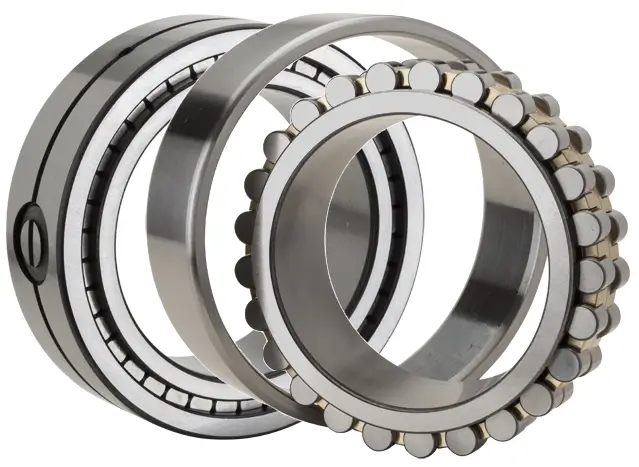
Table of Contents
1. Introduction to Cylindrical Roller Bearings
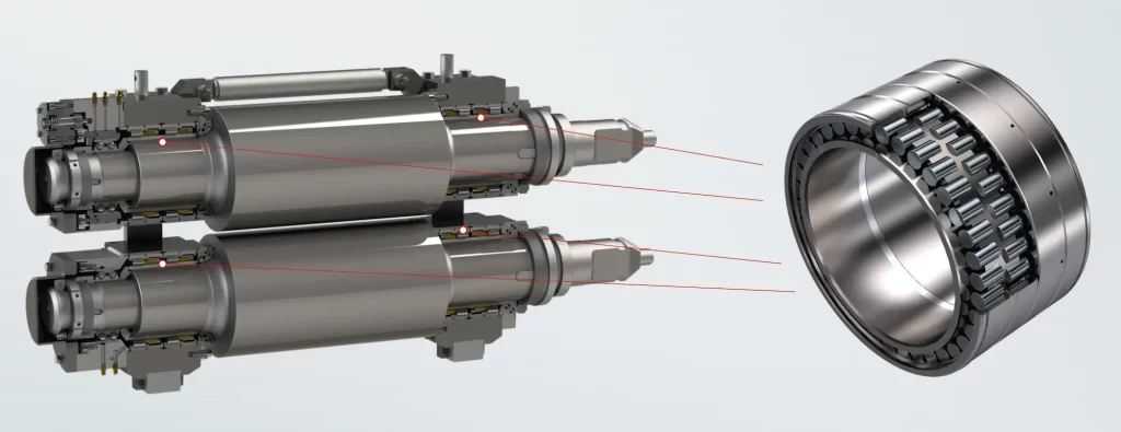
Cylindrical roller bearings (CRBs) represent one of the most fundamental and widely utilized bearing families in modern industrial machinery. Engineered specifically to accommodate high radial loads while maintaining exceptional rigidity, these components are indispensable across sectors ranging from power generation and mining to automotive manufacturing and precision machine tools.
Unlike ball bearings that rely on point contact between the rolling elements and raceways, cylindrical roller bearings utilize line contact. This fundamental geometric distinction enables significantly higher load distribution, making cylindrical roller bearings the preferred choice for heavy-duty applications where radial load capacity is paramount. The rollers are typically crowned or profiled to homogenize stress concentrations and mitigate the effects of misalignment.
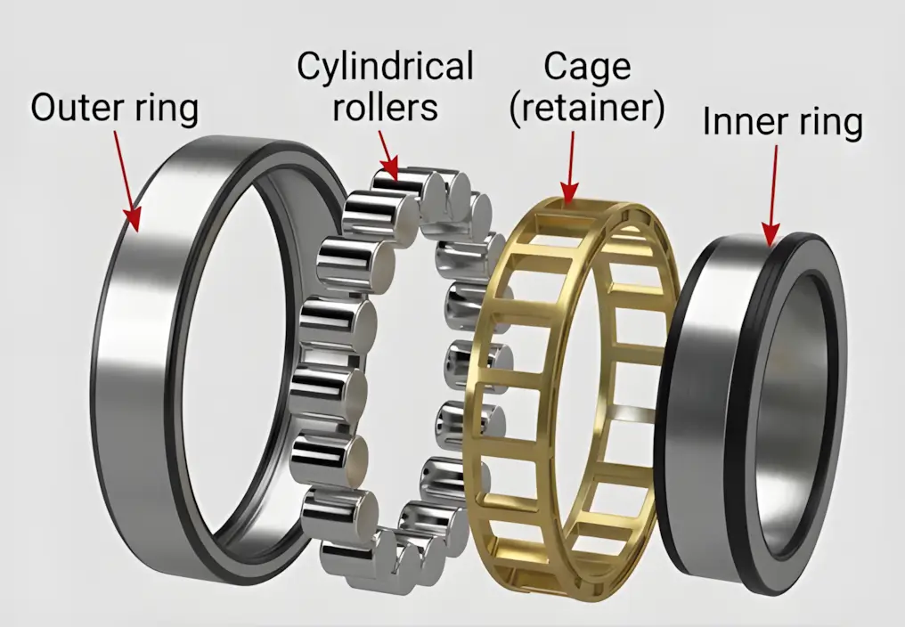
Cylindrical roller bearings feature a relatively simple structure: cylindrical rolling elements maintained in linear contact with the raceways of the inner and outer rings. This design delivers high load capacity under primarily radial loads while maintaining low frictional torque, enabling excellent performance in high-speed applications
2. Classification and Design Variants
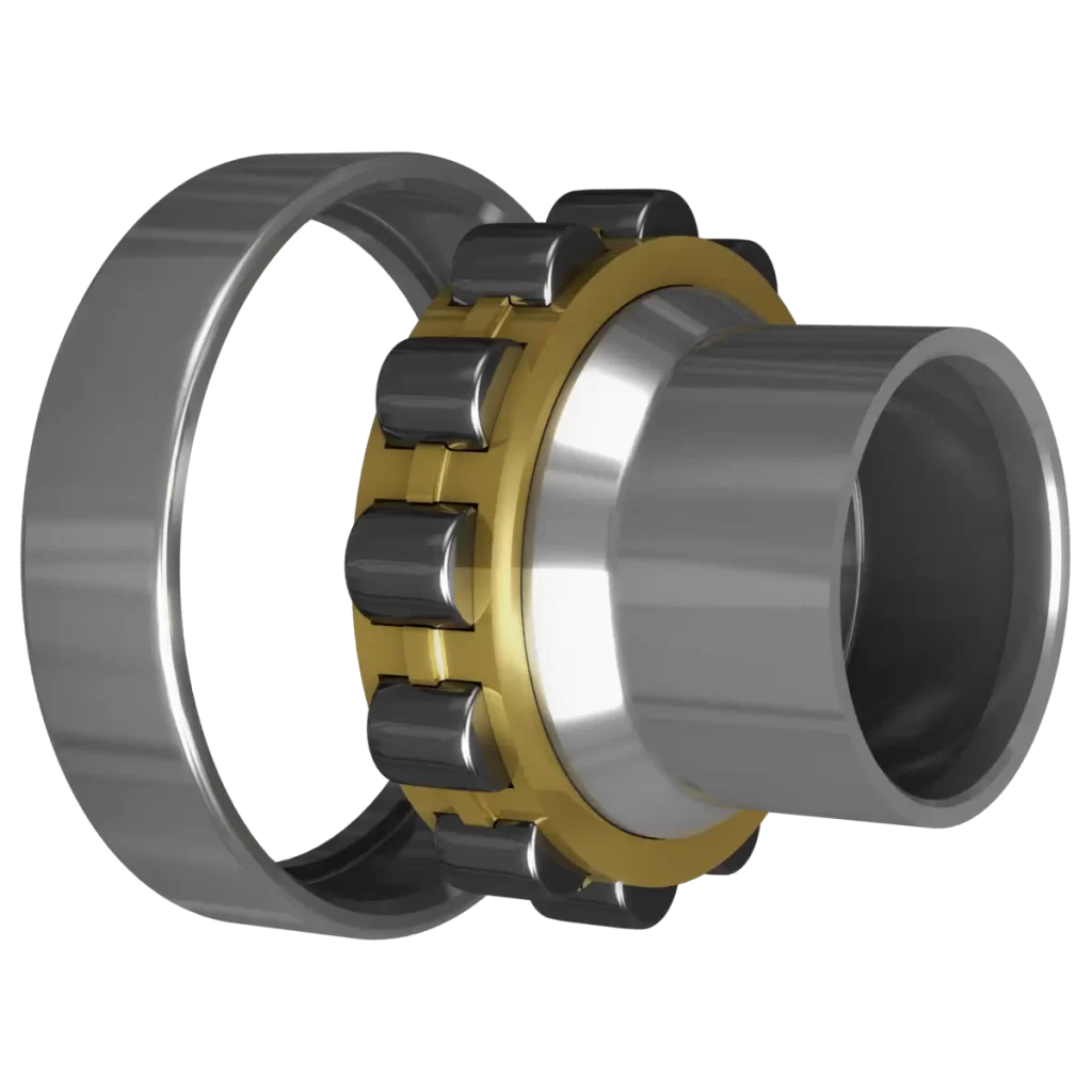
2.1 Single-Row Cylindrical Roller Bearings
Single-row cylindrical roller bearings are designated according to the configuration of flanges (ribs) on the inner and outer rings. These design variations determine whether a bearing can accommodate axial displacement or provide locating functions. The primary types include:
NU Type: Features two integral flanges on the outer ring and a flangeless inner ring. This is a non-locating bearing design that allows the shaft to move axially relative to the housing in both directions, making it ideal for accommodating thermal expansion in long shafts.
N Type: The inverse of the NU design, with two flanges on the inner ring and a flangeless outer ring, permitting axial displacement within the bearing itself.
NJ Type: Equipped with two flanges on the outer ring and one flange on the inner ring. This configuration allows the bearing to provide axial location for the shaft in one direction.
NF Type: Features flanges that can sustain limited axial loads in one direction.
NUP Type: Incorporates two flanges on the outer ring plus one integral flange and one loose flange ring on the inner ring. NUP bearings function as locating bearings, fixing the shaft axially in both directions.
NH Type: Comprises an NJ-type CRB combined with an HJ-type L-shaped thrust collar, suitable for fixed-end bearing applications.
2.2 Double-Row Cylindrical Roller Bearings
Double-row cylindrical roller bearings are designated as NNU or NN, depending on the configuration of side ribs. These bearings offer high radial rigidity and are primarily employed for the main shafts of precision machine tools.
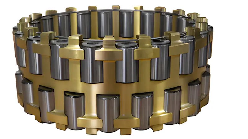
2.3 Full Complement Cylindrical Roller Bearings
Full complement cylindrical roller bearings contain no cage and accommodate the maximum possible number of rollers. This design offers exceptionally high load capacity and rigidity; however, the absence of a cage considerably reduces permissible rotation speeds, and these bearings are only suitable for unidirectional axial loads.
2.4 Thrust Cylindrical Roller Bearings
Cylindrical thrust roller bearings are specifically engineered to receive axial loads while supporting high-load applications with high axial rigidity. Cages are typically manufactured from machined brass
3. Performance Characteristics and Technical Advantages
3.1 Radial Load Capacity
The defining characteristic of cylindrical roller bearings is their superior radial load capacity. The line contact between rollers and raceways distributes loads across a significantly larger surface area compared to the point contact of ball bearings. This allows cylindrical roller bearings to carry substantially greater radial loads within the same spatial envelope. The most heavily loaded cylindrical roller transfers a greater portion of the external radial load than the most heavily loaded ball in an equivalent bearing.
3.2 Frictional Characteristics
Cylindrical roller bearings exhibit very low frictional torque, a characteristic that enables excellent performance in high-speed applications. The low friction between the rollers and ring ribs makes these bearings particularly suited for high-speed rotation. This low-friction performance is maintained across a wide range of operating conditions, contributing to energy efficiency and reduced operating temperatures.
3.3 Speed Capabilities
Cylindrical roller bearings offer high-speed capabilities that are virtually identical to ball bearings of comparable dimensions. The linear contact geometry, combined with optimized cage designs, allows these bearings to achieve high limiting speeds while maintaining load-carrying capacity.
3.4 Axial Load Handling
While primarily designed for radial loads, certain cylindrical roller bearing designs can accommodate moderate axial (thrust) loads. Bearings with flanges (NJ, NF, and NUP types) can sustain limited axial loads in one or both directions. The axial load carrying capacity is not primarily related to the fatigue strength of the material but rather to lubrication conditions and the contact conditions between roller ends and the guiding surface of the flange.
3.5 Rigidity and Precision
Double-row cylindrical roller bearings provide high radial rigidity, making them the preferred choice for precision machine tool spindles. Cylindrical roller bearings are produced according to international standards such as ISO 492 and DIN 620, with precision classes ranging from P0 (Normal) for standard industrial equipment to P6, P5, and P2 for high-speed spindles and precision CNC machinery. Higher precision classes offer tighter tolerances on bore diameter, outside diameter, and running accuracy (radial runout), reducing vibration and heat generation while exponentially extending fatigue life
4. Cage Materials and Their Impact on Performance
The cage (or retainer) maintains the separation and alignment of rollers, significantly influencing the bearing’s speed rating, temperature limit, and vibration levels.
Machined Brass Cages: Offer excellent high-speed performance, very high impact resistance, and operate across a temperature range of -40°C to 250°C. These are frequently selected for demanding environments such as heavy industry, mining, and turbines due to their self-lubricating properties and superior strength-to-weight ratio.
Pressed Steel Cages: Provide good high-speed performance, high impact resistance, and can operate at temperatures up to 300°C. These are the standard for cost-effective, robust performance in high-temperature settings where specialized plastics might fail.
Polyamide (Nylon) Cages: Deliver superior high-speed performance but with moderate impact resistance and a lower maximum operating temperature of 120°C. These are typically used in precision instruments and small motors
5. Industrial Applications
Cylindrical roller bearings are deployed across an extensive range of industries and applications:
Mining and Aggregate Processing: Crushing equipment, conveyors, and screens benefit from the high radial load capacity and shock resistance of cylindrical roller bearings.
Power Generation: Turbines, generators, and auxiliary equipment rely on cylindrical roller bearings for reliable operation under continuous heavy loads.
Cement Processing: Rotary kilns, mills, and crushers utilize cylindrical roller bearings to withstand extreme loads and operating conditions.
Automotive Industry: Engine components, transmissions, wheel hubs, steering systems, and axle assemblies depend on cylindrical roller bearings for high reliability and speed.
Electric Motors and Gearboxes: These represent some of the most common applications, where well-controlled alignment and stable shaft support are maintained.
Machine Tools: High-precision cylindrical roller bearings radially support the main spindles of machine tools, with the entire bearing separable for easy assembly.
Steel and Rolling Mills: Rolling mill rolls, pressure rollers, and continuous-casting machines utilize cylindrical roller bearings for their ability to support extreme radial loads.
Wind Turbines: Gear drives and main shaft assemblies in wind energy applications leverage the high load capacity and reliability of cylindrical roller bearings.
Aerospace: Landing gear systems and engine assemblies employ cylindrical roller bearings where precision and durability are paramount
6. Bearing Selection Criteria
6.1 Load Direction and Magnitude
The primary selection criterion is the nature and magnitude of the loads to be supported. For applications with predominantly radial loads and well-controlled alignment, cylindrical roller bearings represent the optimal choice. Where combined radial and axial loads are present, NJ or NUP types with flanges should be selected.
6.2 Locating vs. Non-Locating Arrangements
In many rotating shaft applications, one bearing should be fixed (locating) while the bearing on the opposite end is free to float (non-locating) to compensate for thermal expansion during operation. Single-row N, NU, and NUB types serve as non-locating bearings, while NJ, NF, and NUP types are designed as locating bearings.
6.3 Speed Requirements
For high-speed applications, bearings with cages (particularly those with polyamide or machined brass cages) should be selected. Full complement designs, while offering maximum load capacity, are unsuitable for high-speed operation.
6.4 Precision Requirements
Standard industrial applications typically utilize P0 (Normal) precision class. For high-speed spindles or precision CNC machinery, P6, P5, or P2 classes are required.
6.5 Operating Temperature and Environment
Operating temperature range, exposure to contaminants, and lubrication conditions all influence bearing selection. Machined brass cages are preferred for high-temperature applications, while sealed or shielded designs may be necessary for contaminated environments.
6.6 Radial Internal Clearance
Standard radial internal clearances are designated as C2, C0 (standard), C3, C4, or C5 according to ISO 5753. C2 represents the minimum clearance and C5 the maximum clearance. Clearance selection must consider the interference fit and expected thermal expansion during operation.
7. Installation and Maintenance Best Practices
7.1 Pre-Installation Inspection
The radial internal clearance of the bearing must be measured before mounting. For tapered bore bearings, the radial clearance reduction is typically determined by measuring the axial displacement of the bearing inner ring relative to the shaft.
7.2 Mounting Procedures
Cylindrical roller bearings feature separable designs that facilitate mounting and dismounting, particularly where interference fits for both rings are necessary. The inner ring and roller elements must be properly seated during installation.
7.3 Clearance Verification
For adjustable clearance bearings (such as NU type), a feeler gauge should be inserted into the gap between the roller and the outer ring, with the depth exceeding half the length of the roller. Clearance and vibration values should be rechecked after the first 100 hours of use, with comprehensive maintenance performed every 2000 hours or six months.
7.4 Common Installation Challenges
The radial clearance after installation is determined by the tolerance of the selected housing bore and shaft. Greater interference results in smaller radial clearance after installation. Misalignment during installation can concentrate stress on rollers and raceways, leading to surface fatigue, increased vibration, and reduced service life. In environments with thermal expansion or varying mounting tolerances, cylindrical roller bearings demand close monitoring and precise installation practices.
8. Failure Modes and Prevention
8.1 Common Failure Mechanisms
Cylindrical roller bearings are susceptible to several failure modes:
Contact Fatigue Spalling: The most common failure type, caused by cyclic stress exceeding the material’s fatigue limit.
Wear: Abrasive wear resulting from contamination or inadequate lubrication.
Fatigue Fracture: Cracking and fracture of bearing components under excessive loading.
Cage Fracture: A common failure mode where the cage structure fails, often due to improper lubrication or excessive loading.
Raceway Defects: Surface damage to the raceways that severely affects bearing contact relationships, cage behavior, skidding, and lubrication.
Overheating: Caused by excessive loads, inadequate lubrication, or improper clearance settings.
Corrosion: Resulting from moisture ingress or improper storage.
8.2 Root Causes
The primary causes of cylindrical roller bearing failure include:
Contamination and improper mounting
Misalignment
Corrosion and inadequate lubrication
Overheating and excessive loads
Improper storage or handling
Improper fit (clearance or interference)
8.3 Prevention Strategies
Preventive measures encompass proper selection, correct installation, adequate lubrication, regular monitoring of vibration and temperature, and scheduled maintenance based on operating hours. Early detection through vibration analysis and condition monitoring can identify developing faults before catastrophic failure occurs.
9. Comparison with Other Bearing Types
9.1 Cylindrical Roller Bearings vs. Ball Bearings
Cylindrical roller bearings offer significantly higher radial load capacity than ball bearings of equivalent size due to line contact versus point contact. Ball bearings, however, typically offer better axial load capacity and can accommodate some misalignment. Speed capabilities are comparable between the two types.
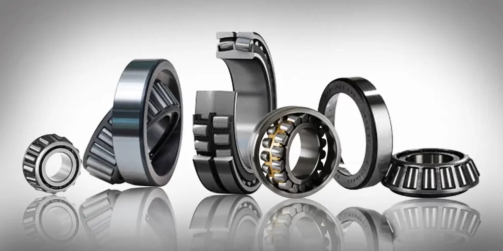
9.2 Cylindrical Roller Bearings vs. Spherical Roller Bearings
Spherical roller bearings feature barrel-shaped rollers that run on a spherical outer raceway, allowing the bearing to self-align as shafts bend or housings shift. They handle both radial and axial loads simultaneously and are valuable where long shafts, structural deflection, and shock loads are present. Cylindrical roller bearings, conversely, are optimized for stable, well-aligned systems focused on radial loads.
9.3 Cylindrical Roller Bearings vs. Tapered Roller Bearings
Tapered roller bearings are designed to manage combined radial and axial loads, with tapered rollers and raceways meeting at a common point along the bearing axis. They require accurate alignment and proper preload. Cylindrical roller bearings, while capable of limited axial loads, are primarily radial load specialists
10. Market Trends and Industry Outlook
The global bearings market demonstrates robust growth, reflecting increasing industrial automation and the integration of predictive maintenance systems. The bearings market was valued at USD 238.60 billion in 2025 and is projected to grow to USD 273.08 billion in 2026, with a CAGR of 15.57%.
Within this broader market, cylindrical roller bearings represent a significant and growing segment. The cylindrical roller bearings market is expected to grow from USD 6.87 billion in 2025 to USD 9.2 billion by 2035, at a CAGR of approximately 3.0%. Super precision cylindrical roller bearings, serving the high-end machine tool and aerospace sectors, are forecast to grow from USD 776 million in 2024 to USD 997 million by 2031.
Key growth drivers include:
Expansion of renewable energy infrastructure (wind turbines)
Electric vehicle manufacturing and automotive electrification
Industrial automation and Industry 4.0 initiatives
Increasing demand for precision machinery
Infrastructure development in emerging economies
Frequently Asked Questions (FAQ)
Q1: What is the primary advantage of cylindrical roller bearings over ball bearings?
Cylindrical roller bearings utilize line contact between rollers and raceways, compared to the point contact of ball bearings. This enables significantly higher radial load capacity within the same spatial envelope. The most heavily loaded cylindrical roller transfers a greater portion of the external radial load than the most heavily loaded ball in an equivalent bearing.
Q2: Can cylindrical roller bearings handle axial loads?
While primarily designed for radial loads, certain designs can accommodate moderate axial loads. NJ, NF, and NUP types with flanges can sustain limited axial loads in one or both directions. The axial load carrying capacity depends on lubrication conditions and the contact conditions between roller ends and the guiding surface of the flange.
Q3: What do the designations NU, NJ, NUP, and N mean?
These designations indicate the flange configuration on the inner and outer rings. NU types have flanges on the outer ring only (non-locating), NJ types have flanges on both rings allowing axial location in one direction, NUP types provide axial location in both directions, and N types have flanges on the inner ring only.
Q4: How should radial internal clearance be selected?
Radial internal clearances are standardized as C2, C0 (standard), C3, C4, or C5 according to ISO 5753. Selection must consider the interference fit and expected thermal expansion during operation. For tapered bore bearings, the radial clearance reduction is determined by measuring the axial displacement of the bearing inner ring.
Q5: What are the most common causes of cylindrical roller bearing failure?
Common failure causes include contamination, improper mounting, misalignment, corrosion, inadequate lubrication, overheating, excessive loads, improper storage or handling, and improper fit. Spalling caused by fatigue is the most common failure type.
Q6: How often should cylindrical roller bearings be maintained?
Comprehensive maintenance should be performed every 2000 operating hours or six months. Clearance and vibration values should be rechecked after the first 100 hours of use.
Q7: What cage material is best for high-temperature applications?
Pressed steel cages can operate at temperatures up to 300°C, making them suitable for high-temperature applications. Machined brass cages operate up to 250°C but offer superior strength-to-weight ratio and self-lubricating properties.
Q8: Are cylindrical roller bearings suitable for high-speed applications?
Yes. Cylindrical roller bearings exhibit very low frictional torque and are capable of performing well in high-speed applications. Their speed capabilities are virtually identical to ball bearings of comparable dimensions.
Q9: What is the difference between locating and non-locating bearings?
In rotating shaft applications, one bearing is fixed (locating) to establish axial position, while the bearing on the opposite end is free to float (non-locating) to compensate for thermal expansion. NU and N types serve as non-locating bearings; NJ, NF, and NUP types are locating bearings.
Q10: Why choose MYWAY for cylindrical bearing requirements?
MYWAY brings over 20 years of manufacturing expertise, IATF 16949 and ISO 9001 certifications, three vertically integrated production facilities totaling 35,000 m², custom engineering capabilities, and a comprehensive product portfolio including bearings, bushings, and fasteners. The company serves customers in over 40 countries and offers a one-year warranty on all products
100000+ Types of Bushings – Contact Us for Details