
Recent Posts
The Silent Language of Precision: Mastering Shaft and Hole Tolerances & Fits for Maximum Equipment Reliability
Introduction
Behind every smooth-running machine lies a language that most operators never see—the silent, precise language of shaft and hole tolerances. Every rotating shaft, every reciprocating piston, and every bushing that supports them speaks this language. When the tolerances are right, the conversation is seamless. When they‘re wrong, the results range from excessive friction to catastrophic seizure.
For engineers responsible for plain bearings and bushings—the unsung workhorses of heavy machinery—understanding tolerance of fit isn’t just a design exercise. It’s the difference between a component that outlasts the equipment and one that fails before its first scheduled maintenance. This guide demystifies the ISO tolerance system, delivers practical fit selection strategies, and explains how modern self-lubricating bushing technologies from MYWAY can help you achieve the ideal fit that maximizes reliability while minimizing maintenance.
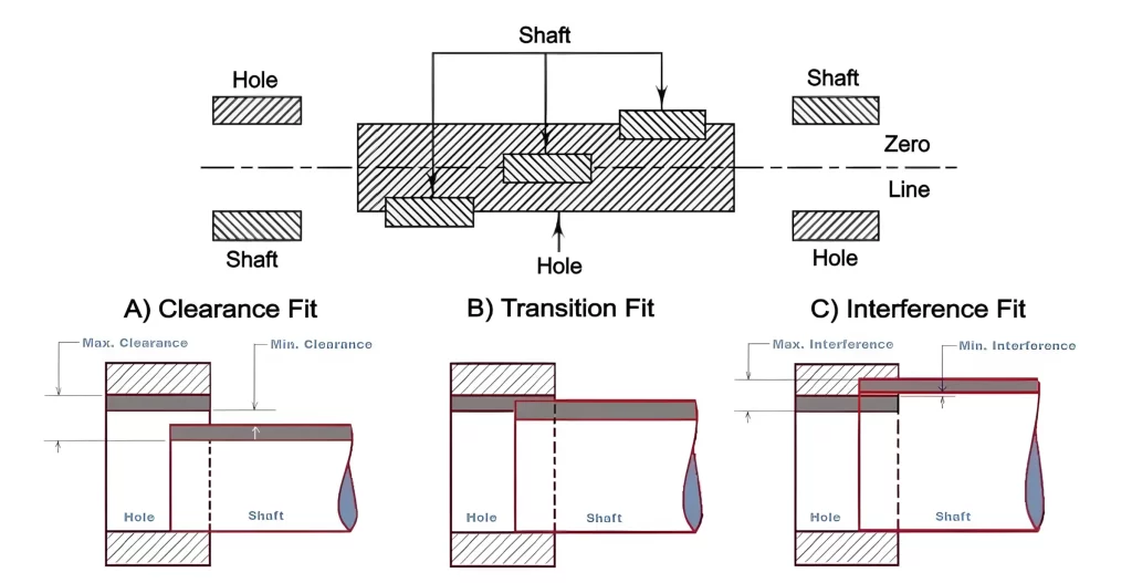
Table of Contents
1: Why Tolerance of Fit Makes or Breaks Your Equipment
Tolerance defines the permissible variation in a manufactured dimension. Fit describes how two mating parts—a shaft and a hole, a bushing and its housing—relate to each other once assembled.
For a plain bearing or bushing system, three critical interfaces demand attention:
OD-to-Housing Fit: How firmly the bushing seats in its housing bore
ID-to-Shaft Fit: How freely the shaft rotates or slides inside the bushing
Thermal and Load Behavior: How the fit changes under real operating conditions
Specifying the wrong fit causes a cascade of failures. An outer diameter that’s too loose allows the bushing to spin or fret, chewing into the housing wall and generating debris that accelerates wear throughout the system.An inner diameter that’s too tight creates excessive friction, overheating, and eventual seizure. An inner diameter that’s too loose introduces vibration, misalignment, and impact loading that shortens service life.
When specified correctly, however, controlled clearances deliver:
Predictable friction and optimized lubrication film thickness
Even load distribution across the entire bearing surface
Efficient heat transfer from friction zones to the housing
Extended wear life and reduced downtime
Reliable positional accuracy under dynamic loads
The cost of getting it wrong is measured in unplanned downtime, emergency parts replacement, and lost production revenue.
2: Tolerance Zones and the Hole Basis System
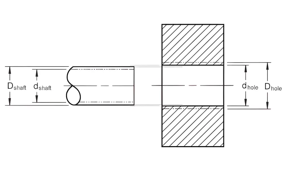
Every dimension has a permissible variation known as a tolerance. When a shaft and a hole share the same basic size but have different tolerance zones, the way those zones overlap defines the resulting fit.
The international standard for limits and fits is ISO 286, which uses letter-number combinations to specify tolerance zones. The letter indicates the position of the tolerance zone relative to the basic size (uppercase for holes, lowercase for shafts), and the number indicates the grade of tolerance (how wide the zone is). For example, H7 designates a hole whose lower deviation is exactly at the basic size, with a width determined by the IT7 grade.
The Hole Basis System (Most Common, Especially for Bushings)
This system fixes the housing bore as the reference. The hole‘s lower deviation is set to zero (the “H” position), and different fits are produced by adjusting the shaft’s tolerance zone.
Why hole basis? Hole sizes are typically established using standard drills or reamers, making holes more difficult to vary precisely compared to shafts. By keeping the hole constant, manufacturers can use standardized tooling while achieving a full range of fits through shaft variations alone.
The Shaft Basis System
Used when shaft sizes are fixed or standardized. The shaft‘s upper deviation is set to zero (the “h” position), and the hole’s tolerance zone is varied. This approach is less common for bushing applications but appears in specialized shaft-first designs.
3: The Three Types of Fits—Clearance, Interference, Transition
3.1 Clearance Fit
In a clearance fit, the maximum shaft size is smaller than the minimum hole size. Even under worst-case manufacturing conditions, an intentional gap remains.
Characteristics:
Always measurable clearance
Very low friction operation
Simple, tool-free assembly
Allows free rotation or sliding
Applications in Bushings:
Rotating shafts inside bronze or polymer bushings
Sliding sleeves and linear motion systems
Oscillating joints requiring smooth movement
Applications where thermal expansion will reduce clearance
Typical ISO Pairings: H7/g6, H7/f7, H7/h6, H9/d9
3.2 Interference Fit
An interference fit exists when the minimum shaft diameter is always larger than the maximum hole diameter.The shaft is intentionally oversized relative to the hole, creating a press-fit or shrink-fit connection.
Characteristics:
Always interference—no gap exists
High holding strength without additional fasteners
No relative motion between components
Requires pressing, heating, or cooling for assembly
Difficult or destructive disassembly
Applications in Bushings:
Press-fitting bushings into housings (the standard method)
High-load structural joints where movement would cause fretting
Torque-transmitting hubs and couplings
Typical ISO Pairings: H7/p6, H7/r6, H7/s6, H7/u6
3.3 Transition Fit
A transition fit occurs when the tolerance zones overlap. The actual manufactured parts may produce either a slight clearance or a slight interference, depending on how the dimensions fall within their tolerance ranges.––
Characteristics:
May result in small clearance or light interference
Provides accurate centering and alignment
Requires light assembly force (often hand or light press)
Easier to disassemble than full interference fits
Ideal for precision location applications
Applications in Bushings:
Locating shoulders and spigots
Centering pins and precision sleeves
Components requiring accurate positioning with manageable assembly effort
Typical ISO Pairings: H7/k6, H7/js6, H7/m6
Comparison Table: Clearance vs. Interference vs. Transition Fits
| Feature | Clearance Fit | Interference Fit | Transition Fit |
|---|---|---|---|
| Resulting Condition | Always clearance | Always interference | Clearance or interference |
| Tolerance Zone Overlap | No overlap | No overlap | Overlap exists |
| Assembly Method | Hand assembly | Force or temperature | Light force |
| Relative Movement | Allowed | Prevented | Minimal or none |
| Typical Purpose | Smooth rotation | Permanent anchoring | Precise alignment |
| ISO Pairing Examples | H7/g6, H7/f7, H7/h6 | H7/p6, H7/r6, H7/s6 | H7/k6, H7/js6, H7/m6 |
4: Material Selection and Its Impact on Tolerance Decisions
The material of a self-lubricating bearing significantly influences the tolerances required for a given application. Different materials have varying degrees of thermal expansion, wear resistance, and installation behavior.–
Bronze Bushings
Bronze remains the most common material for self-lubricating bushings due to its excellent wear resistance, high load capacity, and low friction properties against steel shafts. Cast bronze offers exceptional load-bearing capability while bronze alloys provide good corrosion resistance.
Tolerance Considerations for Bronze:
Bronze has a coefficient of thermal expansion (CTE) of approximately 17–19 × 10⁻⁶ /K, higher than typical carbon steel shafts (11–13 × 10⁻⁶ /K).
At elevated operating temperatures, bronze bushings expand more than steel shafts, potentially increasing running clearance.
PTFE bronze bushings combine the strength of bronze with PTFE’s ultra-low friction coefficient of 0.05–0.10, reducing shaft wear even when clearances are optimized for tighter operation.
Self-Lubricating vs. Grease-Lubricated
Traditional oil- or grease-lubricated bearings require regular lubrication schedules that add labor costs, downtime, and the risk of human error. MYWAY PTFE bronze bushings are completely self-lubricating, with PTFE plugs or liners that provide permanent lubrication for the life of the bearing.This self-lubricating property—combined with precise tolerance control—eliminates lubrication-related clearance variations and ensures consistent performance across the bushing‘s service life.
5: Recommended Fit Selections for Bushings
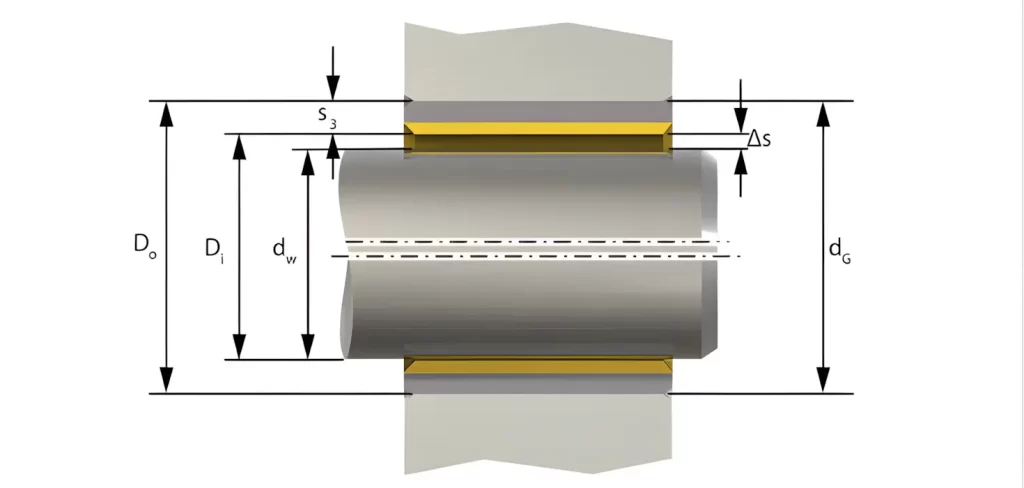
Bushing systems have two independent fit interfaces that must be specified separately.
5.1 Outer Diameter Fit—Bushing to Housing
A bushing must be rigidly supported in its housing to avoid rotation, distortion, or fretting. For this reason, interference fits are the standard for the outer diameter of press-fit bushings.
MYWAY Recommended OD Fit: H7/p6 or H7/r6
Why This Works:
Creates guaranteed interference regardless of manufacturing variation
Prevents spinning and chewing into the housing wall
Ensures optimum heat transfer through tight metal-to-metal contact
Maintains bushing roundness under load
The press fit accomplishes several critical goals: it locks the bushing radially to prevent creep or rotation under load, provides uniform radial support around the entire bushing wall, and creates an efficient thermal path for heat dissipation from friction.
5.2 Inner Diameter Fit—Shaft to Bushing
Shafts operating inside bushings require controlled clearance for lubrication distribution, thermal expansion accommodation, and smooth rotation.
MYWAY Recommended ID Fit: H7/g6 or H7/f7 for rotating shafts; h9 for applications where the shaft is stationary and the housing rotates
Why This Works:
Low friction operation with predictable lubrication thickness
Reduced risk of seizure at elevated temperatures
Accommodates thermal expansion differences between shaft and bushing
Maintains hydrodynamic or mixed lubrication regime
For self-lubricating bushings, the standard industry recommendation is an H7 housing bore and a shaft tolerance of h6 to h9.– When bushings are press-fit into an H7 housing, the inner diameter is calibrated to achieve the final ID tolerance (typically H7 or H8) after installation.
5.3 Transition Fits for Alignment-Critical Applications
When the assembly must locate components precisely but still allow manageable assembly forces, transition fits are the ideal choice.
Common ISO Pairings: H7/k6, H7/js6, H7/m6
Applications:
Locating shoulders and spigots requiring centering accuracy
Components that need precise positioning with occasional disassembly
Multi-bushing housings where alignment across multiple bores is critical
6: Thermal Expansion—The Hidden Variable in Fit Selection
One of the most overlooked factors in fit selection is thermal expansion. During operation, temperature changes alter the diameters of both the shaft and the bushing. If these changes aren‘t accounted for during the design phase, the intended fit can shift unexpectedly.
How Thermal Expansion Affects Fits
Clearance Fit at Room Temperature: At high temperatures, bushings may expand more than the shaft, increasing clearance and reducing load-bearing capacity.
Interference Fit at Room Temperature: If the bushing expands more than the shaft, interference increases, raising frictional heat and seizure risk.
Dissimilar Materials: When bronze bushings (CTE ~17–19 × 10⁻⁶/K) operate with steel shafts (CTE ~11–13 × 10⁻⁶/K), the differential expansion changes the effective clearance by approximately 6–8 × 10⁻⁶/K per degree.
Practical Design Adjustments for Temperature
Increase initial clearance for high-temperature applications where the shaft and bushing materials have mismatched CTEs
Calculate clearance change using the formula: ΔD = D₀ × (α_bushing – α_shaft) × ΔT
Consider steel-backed bushings when operating temperatures are high and CTE mismatches are significant
Use tapered fits when extreme temperature cycling is expected
For internal combustion engine applications, clearance in high-temperature copper sleeves can reach 0.1 mm at operating temperature to accommodate expansion.
7: Press Fit Tolerancing for Bushings—Practical Guidelines
Press-fit bushing installation relies on interference between the bushing‘s outside diameter and the housing bore. The bushing OD is manufactured slightly larger than the housing ID, and the press creates an interference fit that holds the bushing securely.
Standard Approach Using H7 Hole Basis
In the nearly universal hole basis system for bushing press fits:
Housing bore is machined to H7 tolerance (lower deviation at basic size, IT7 grade tolerance width).
Bushing OD is manufactured with a tolerance zone entirely above the H7 tolerance zone—even the smallest possible bushing OD is still larger than the largest possible H7 hole.
The result is guaranteed interference for all manufactured parts within specification.
Common ISO Press Fit Combinations
| Housing Bore | Bushing OD | Fit Type | Application |
|---|---|---|---|
| H7 | p6, r6, s6 | Interference (Press) Fit | Permanent anchoring, high-load applications |
| H7 | n6, m6 | Transition Fit | Precise location with possible disassembly |
| H7 | h6, g6, f7 | Clearance Fit | Sliding or rotating shaft applications |
Material-Specific Considerations
For bronze bushings, press-fit interference must be balanced: too little interference allows spinning and fretting; too much interference distorts the inner bore, reducing running clearance and creating high-friction zones.When MYWAY bronze bushings are pressed into an H7 housing, the bore is calibrated after installation to achieve the final ID tolerance—typically H7 or H8 depending on the size range.
8: Engineering Case Study—Heavy Machinery Pivot Arm
Scenario: A bronze plain bearing with nominal 30 mm outer diameter and 20 mm inner diameter is being designed for a heavy machinery pivot arm subject to shock loads and oscillating motion.
Step 1—Selecting the OD Fit (Bushing to Housing)
The bushing must withstand shock loading and maintain perfect alignment without rotation or fretting. Recommended fit: H7/p6 interference fit.
Step 2—Selecting the ID Fit (Shaft to Bushing)
The shaft rotates under mixed lubrication conditions with moderate temperature rise. Recommended fit: H7/g6 clearance fit.
Resulting Benefits:
Strong mechanical locking of the bushing prevents spinning under dynamic loads
Smooth shaft rotation with predictable friction coefficient
Controlled lubrication gap maintains proper oil film thickness
Thermal expansion accommodation prevents seizure at operating temperature
Stable performance across the equipment‘s entire service life
9: MYWAY—Precision Self-Lubricating Bronze Bushings Engineered for the Perfect Fit
At MYWAY, we understand that tolerance of fit is not a secondary specification—it’s the foundation of bushing performance. Every MYWAY self-lubricating bronze bushing is manufactured with precision tolerances that deliver the exact fit your application demands.
Why Engineers Choose MYWAY
PTFE Bronze Bushings for Maintenance-Free Operation
MYWAY PTFE bronze bushings combine the exceptional strength and durability of cast bronze with the ultra-low friction properties of PTFE. PTFE provides permanent solid lubrication with a coefficient of friction as low as 0.05, eliminating the need for external grease or oil schedules. This self-lubricating property ensures consistent running clearance across the bushing’s entire service life.
Leaded Bronze for High-Load, Low-Speed Applications
For applications requiring high-load capacity with marginal lubrication, MYWAY leaded bronze bushings provide built-in lubricity through lead particles that migrate to the bearing surface, creating a thin sacrificial film that reduces friction. These bushings excel in heavy industrial machinery, mining equipment, and agricultural applications.
Custom Tolerances for Your Exact Requirements
Every MYWAY bushing can be manufactured to your specific tolerance requirements. Need a unique wall thickness? Special oil groove pattern? Non-standard OD or ID tolerance? MYWAY’s advanced manufacturing capabilities deliver precision-engineered bushings that fit your housing and shaft exactly.
MYWAY Product Capabilities
Materials: Bronze alloys (C93200, C95400, C86300), PTFE-impregnated bronze, leaded bronze, graphite bronze
Self-Lubricating Technology: Solid lubricant plugs, liners, or impregnated matrix
Temperature Range: From cryogenic -268°C to high-temperature 327°C
Tolerance Control: Precision machining to H7, h6, g6, f7, p6, r6 standards
Industries Served: Heavy machinery, mining, construction, marine, offshore, hydropower, agriculture, automotive
10: Conclusion
Correctly selecting shaft and hole tolerances for plain bearings and bushings is essential for achieving reliable, long-lasting equipment performance. A deep understanding of tolerance zones, basis systems, and fit types gives engineers the power to control friction, assembly method, alignment accuracy, and load capacity.
Mastering these principles ensures that components assemble correctly, operate efficiently, and maintain precision throughout their service life. When combined with high-quality self-lubricating bronze bushings from MYWAY, the result is a bearing system that minimizes downtime, extends service life, and reduces total cost of ownership.
Frequently Asked Questions (FAQ)
Q1: What is the difference between H7/g6 and H7/h6? Which should I use for a rotating shaft?
H7/g6 provides a slightly tighter clearance than H7/h6, making it better suited for rotating shafts that require precise positioning. H7/h6 provides more generous clearance for freer movement. For most rotating shaft applications in bronze bushings, H7/g6 is the recommended starting point.
Q2: How much press-fit interference is needed for a bronze bushing in a steel housing?
The required interference depends on bushing size, wall thickness, and operating conditions. For standard applications, ISO pairings H7/p6 or H7/r6 provide guaranteed interference. For more precise calculations, use the formula: ΔD = (housing ID upper limit) – (bushing OD lower limit). A typical guideline is 0.001–0.002 inches per inch of diameter, but always verify using ISO tolerance tables for your specific dimensions.
Q3: What happens if a bushing is pressed in with too much interference?
Excessive interference distorts the bushing‘s inner bore, reducing running clearance and creating localized high-friction zones. This leads to overheating, accelerated shaft wear, and potential seizure.The press force also transfers fully into the housing wall, potentially cracking thin-walled housings.
Q4: How do I account for thermal expansion when selecting shaft tolerances for high-temperature applications?
Calculate the effective clearance change using ΔD = D₀ × (α_bushing – α_shaft) × ΔT. Bronze expands more than steel (typically 6–8 × 10⁻⁶/K difference). For every 100°C temperature rise, a 20 mm diameter bronze-steel pair experiences approximately 0.012–0.016 mm of additional clearance. Increase initial room-temperature clearance accordingly.
Q5: Can self-lubricating bronze bushings be used without any external lubrication?
Yes. MYWAY PTFE bronze and leaded bronze bushings are specifically designed for maintenance-free operation. The embedded solid lubricants (PTFE or lead) provide permanent lubrication for the life of the bearing, even in start-stop or boundary lubrication conditions.
Q6: What shaft surface finish is recommended for MYWAY bronze bushings?
For optimal performance with bronze bushings, shaft surfaces should be ground to Ra 0.4–0.8 µm (16–32 µin). Hardened steel shafts (55 HRC or higher) significantly extend bushing life, especially in high-load or abrasive environments.
Q7: How do I select the right fit if my bushing is pressed into a plastic or aluminum housing?
Plastic and aluminum housings have different thermal expansion and elastic properties than steel. For aluminum housings, reduce interference by approximately 20–30% compared to steel to avoid bore distortion. For plastic housings, use a light transition fit (H7/k6) or even a clearance fit with mechanical retention features, as plastics cannot sustain high press-fit stresses without deforming.
Q8: What does the “H7” tolerance mean in real numbers?
H7 defines a hole whose lower deviation is exactly at the basic size (zero) and whose upper deviation equals the IT7 tolerance grade value. For a 20 mm hole, IT7 = 21 micrometers, so the hole tolerances are 0 to +0.021 mm.
Q9: Why does my bushing’s inner diameter shrink after press-fitting?
When a bushing is pressed into a smaller housing, the bushing wall compresses radially, reducing its inner diameter. This is called “bore reduction.” For MYWAY press-fit bushings, the final ID tolerance is calibrated after installation to account for this effect. Always follow the manufacturer’s housing bore recommendation (typically H7) and specified post-press ID tolerance.
Q10: How do I request a custom MYWAY bushing with specific tolerances for my application?
Contact MYWAY‘s engineering team with your shaft diameter, housing bore dimensions, operating temperature range, load conditions, and application environment. MYWAY provides custom tolerance machining, non-standard sizes, specialized materials, and unique lubricant configurations to match your exact requirements.
100000+ Types of Bushings – Contact Us for Details